- 首页
- » 搜索
- » XIVN1987 发表的帖子
#3 Re: 工业芯 匠芯创 » 有没有好用迷你的程序和gui工具推荐? » 2024-04-23 08:55:55
#7 RISC-V » RISC-V CLINT 中断处理与中断嵌套 » 2024-04-15 09:43:37
- XIVN1987
- 回复: 0
volatile int timer_n = 0;


void timer_handler (void) {
    timer_n++;
}

timer_handler:
    lui     a0, %hi(timer_n)
    lw      a1, %lo(timer_n)(a0)
    addi    a1, a1, 1
    sw      a1, %lo(timer_n)(a0)
    ret


__attribute__((interrupt))
void timer_handler (void) {
    timer_n++;
}

timer_handler:
    addi    sp, sp, -16
    sw      a0, 12(sp)                      # 4-byte Folded Spill
    sw      a1, 8(sp)                       # 4-byte Folded Spill
    lui     a0, %hi(timer_n)
    lw      a1, %lo(timer_n)(a0)
    addi    a1, a1, 1
    sw      a1, %lo(timer_n)(a0)
    lw      a0, 12(sp)                      # 4-byte Folded Reload
    lw      a1, 8(sp)                       # 4-byte Folded Reload
    addi    sp, sp, 16
    mret
对比发现,添加 __attribute__((interrupt)) 修饰后,编译器给用到的寄存器添加保存、恢复代码,并将 ret 替换为 mret.
既然 ISR 对自己使用的寄存器都会提前保存、返回时恢复,,那么发生中断嵌套就不会破坏 ISR 的上下文环境,,可以允许中断嵌套的发生
但是在中断返回时 CPU 需要 mepc 和 mstatus 中的信息确定返回地址和返回特权级,,这些寄存器编译器没有给我们保存、恢复,,因此还需要手动添加代码处理
__attribute__((interrupt))
void timer_handler (void) {
    int mepc, mstatus;

    asm("csrr %0, mepc\n\t"
        "csrr %1, mstatus\n\t"
        "csrsi mstatus, 8"      // mstatus.MIE = 1, interrupt enable
        : "=r" (mepc), "=r" (mstatus));

    // ISR code

    asm("csrci mstatus, 8\n\t"  // mstatus.MIE = 0, interrupt disable
        "csrw mepc, %0\n\t"
        "csrw mstatus, %1"
        : : "r" (mepc), "r" (mstatus));
}
实现中断嵌套的关键是在重新使能中断之前保存 mepc、mstatus,并在执行 mret 之前恢复它们
但在 CLINT 下实现中断嵌套没有意义,因为 CLINT 下没有中断优先级,中断嵌套只有配合可配置的中断优先级才有意义。所以一般 MCU 厂商会使用更高级的中断控制器替代 CLINT,而不会直接使用官方简陋的 CLINT,,比如沁恒 MCU 使用了自己设计的 PFIC 中断控制器,,添加了中断优先级等功能。。
#8 RISC-V » RISC-V 如何实现 __disable_irq()? » 2024-04-12 13:51:39
- XIVN1987
- 回复: 6
之前一直以为 mstatus.MIE 可以用作中断的全局总开关,,仔细看了 spec 才发现并不能
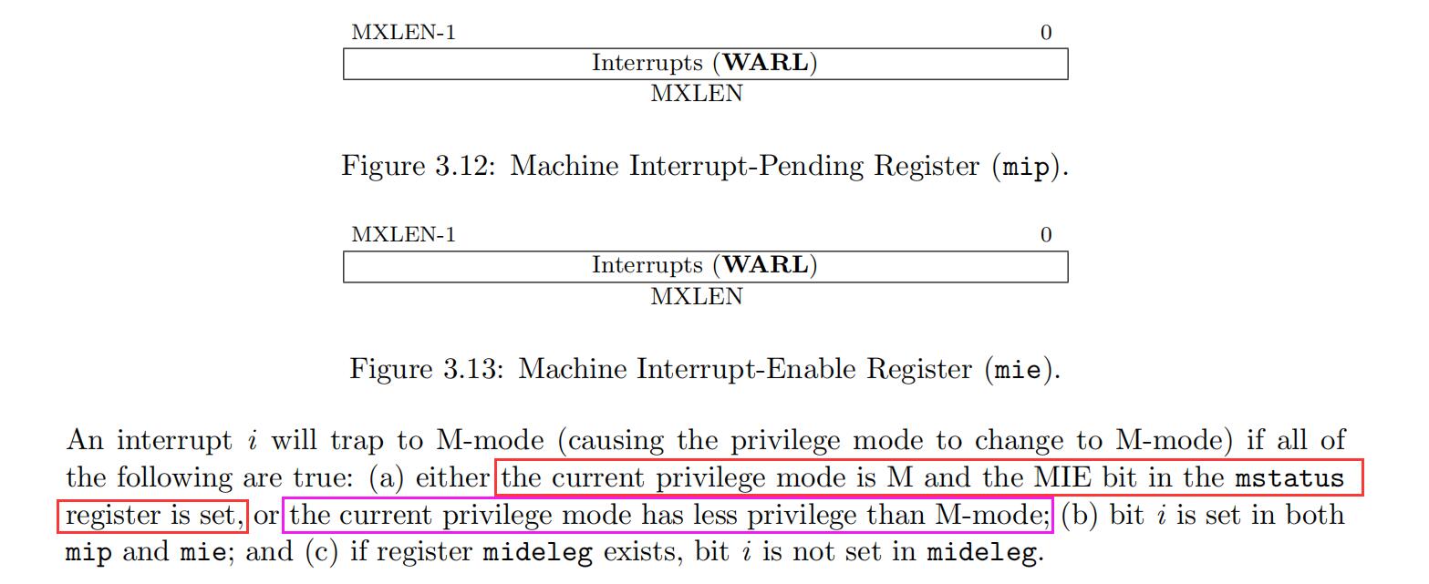
根据下面这说法,,如果程序正在用户模式执行,,然后来了中断,,即使 mstatus.MIE == 0,也会切换到机器模式去执行中断处理函数。。
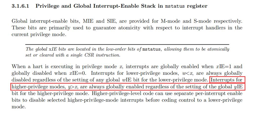
所以 RISC-V spec 里面并没有一个全局关闭中断的方法,,
查看沁恒驱动库中的 __disable_irq() 实现可以看到,,它是通过地址为 0x800 的 CSR 寄存器实现的,,而这个地址属于“User-Level Custom read/write”区,,也就是说,这是一个芯片厂商自定义的寄存器
RV_STATIC_INLINE void __disable_irq()
{
  __asm volatile ("csrw 0x800, %0" : : "r" (0x6000) );
}#12 Re: 工业芯 匠芯创 » D211DCV+W25N01GVZEIG 烧录固件不成功问题求助 » 2024-03-23 15:29:02
https://whycan.com/t_10422.html
我之前画了一块也是无法烧录,,怀疑是不是因为 SDNAND 连线没画等长,,看你这个画了等长还是烧录失败,,不好搞。。
#17 Re: Php/Nodejs/Web/HTML5/Javascript/微信开发/Python » 如何使用 Pyserial 访问 OrangePi 3B 的串口 » 2024-03-17 17:14:31
搜了下,,发现这个问题四年前就有人提了,,可惜还没解决。。有人提了 pr,,但作者还未 merge
#18 Php/Nodejs/Web/HTML5/Javascript/微信开发/Python » 如何使用 Pyserial 访问 OrangePi 3B 的串口 » 2024-03-17 12:03:19
- XIVN1987
- 回复: 3
使用 orangepi-config 使能 UART2 后,,在 /dev 下可以看到 ttyS2,,但如下代码查询结果为空:
In [10]: from serial.tools.list_ports import comports

In [11]: comports()
Out[11]: []
查看 comports 实现如下: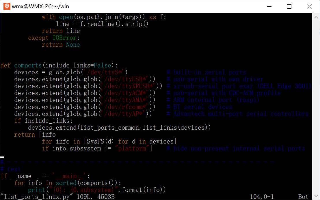
逐句执行 comports 语句:
In [16]: glob('/dev/ttyS*')
Out[16]: ['/dev/ttyS9', '/dev/ttyS7', '/dev/ttyS2', '/dev/ttyS1']

In [17]: [SysFS(d) for d in _]
Out[17]:
[<serial.tools.list_ports_linux.SysFS at 0x7f88996830>,
 <serial.tools.list_ports_linux.SysFS at 0x7f88997550>,
 <serial.tools.list_ports_linux.SysFS at 0x7f889979d0>,
 <serial.tools.list_ports_linux.SysFS at 0x7f889a54e0>]

In [18]: [d.subsystem for d in _]
Out[18]: ['platform', 'platform', 'platform', 'platform']
可知 comports 是识别出了串口 ttyS2 的,,但又因为它的 subsystem 属性值为 platform,,又把它丢弃了。。
不知道这是 pyserial 的问题,,还是 OrangePi 系统的问题,,怎样修改才比较合理??
#19 Re: 全志 SOC » ARM 开发指令 对于嵌入式开发 重要吗 » 2024-02-23 11:27:46
#22 Re: RISC-V » 国产riscv芯片汇总 » 2024-01-28 21:47:17
#26 Re: DIY/综合/Arduino/写字机/3D打印机/智能小车/平衡车/四轴飞行/MQTT/物联网 » 花了小半天 搭了个全新版本 eclipse + gcc ... » 2023-12-26 22:26:57
#27 Re: 计算机图形/GUI/RTOS/FileSystem/OpenGL/DirectX/SDL2 » rtthread 初始化阶段中断开关是不是有问题? » 2023-12-26 15:49:40
#28 计算机图形/GUI/RTOS/FileSystem/OpenGL/DirectX/SDL2 » rtthread 初始化阶段中断开关是不是有问题? » 2023-12-26 15:07:53
- XIVN1987
- 回复: 3
rtthread_startup() => rt_hw_local_irq_disable() 关闭了全局中断
rt_system_scheduler_start() => rt_hw_context_switch_to() => CPSIE I 开启了全局中断
上述开关中断流程,我觉得没有问题。。
但是在二者之间,有如下的调用流程
rt_hw_board_init()
    => rt_system_heap_init()
        => rt_memheap_init()
            => rt_object_init()
                => rt_spin_unlock_irqrestore
                    => rt_hw_interrupt_enable
又把全局中断打开了,,既然中间会打开全局中断,,那一开始的关闭全局中断又有什么意义呢??
#29 工业芯 匠芯创 » 求教,,使用AiBurn烧录,,D211不读写SPINAND直接报错烧录失败,, » 2023-12-16 16:15:48
- XIVN1987
- 回复: 1
首先,,复位之后,,D211是有通过SPI0读取SPINAND的动作的,,说明D211和SPINAND的物理连接没有问题
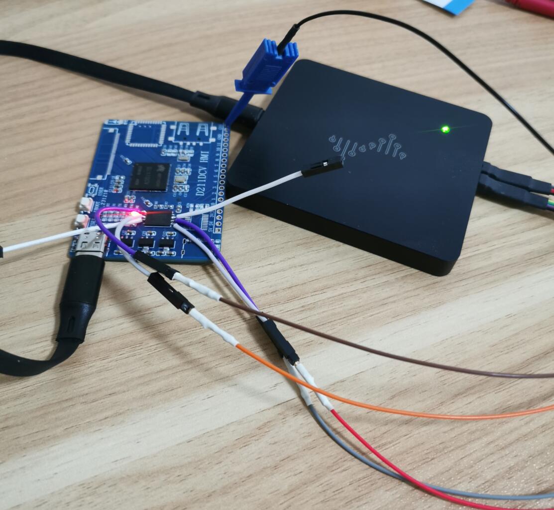
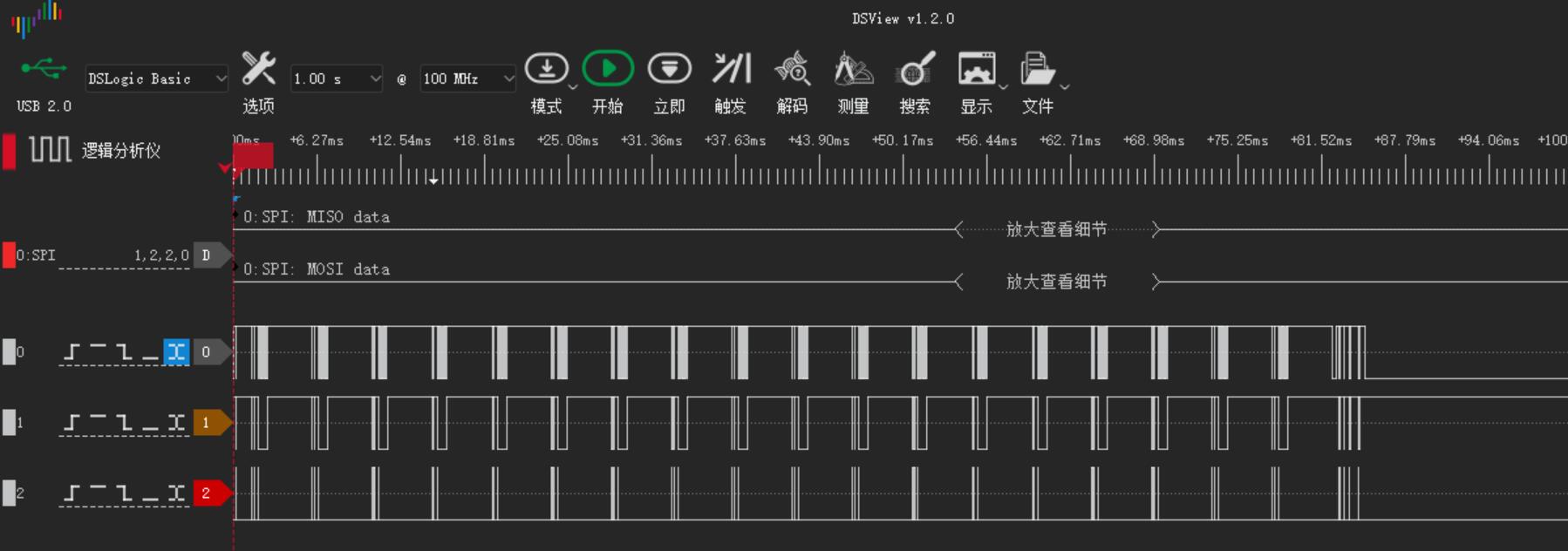
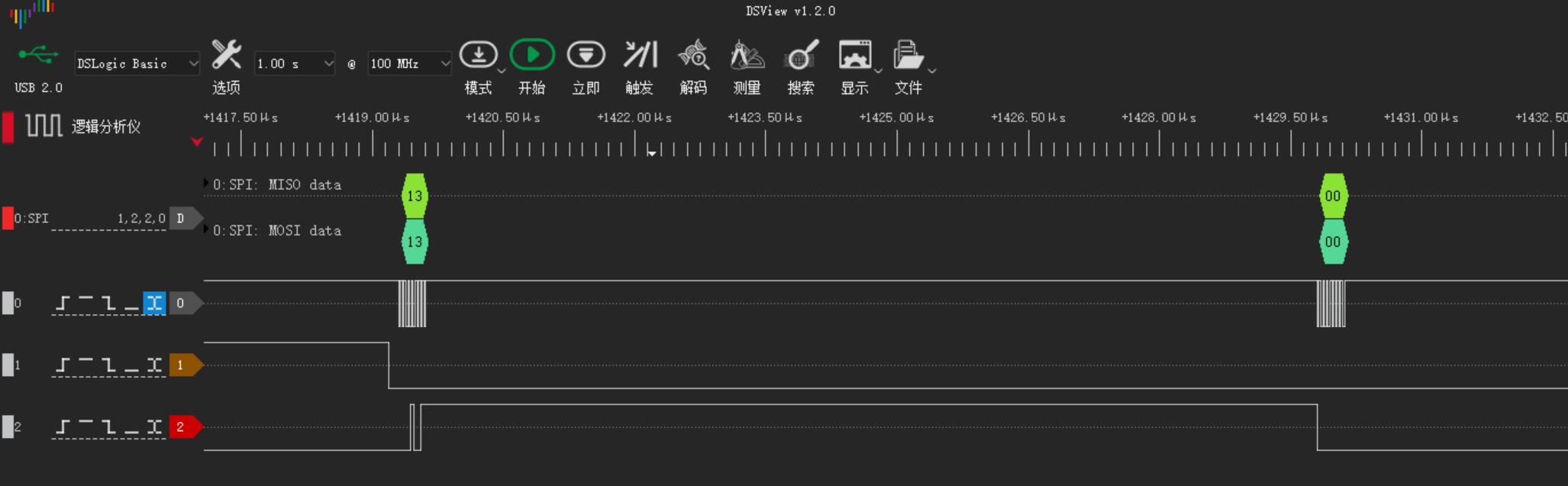
注意:100MHz 采样率下我的逻辑分析仪只能抓取 3 个信号,,所以未抓取 MISO 信号,,请忽略
然后AiBurn中按下“开始”按钮,,烧录失败,,log 内容如下,,但烧录过程中 SPI0 上完全没有任何信号,,请问这个是什么原因??
[debug] Software Version: "1.3.4"
[debug] Machine Name: "WMX-PC"
[debug] System Name: "Windows 10 (10.0)"
[debug] CPU Architecture: "x86_64"

[debug] Parse the image header from "C:/Users/WMX/Desktop/d211_demo100_nand_page_2k_block_128k_v1.0.0.img"
[debug] Soc type: "d211"
[debug] Board type: "demo100_nand_page_2k_block_128k"
[debug] Image version: "1.0.0"
[debug] Storage type: "spi-nand"
[debug] Storage ID: "P=2K,B=128K"
[debug] Meta count: "13"

[debug] Refresh the partition tree ...
[debug] Part name: image.target.spl , size: 128528
[debug] Part name: image.target.uboot , size: 826603
[debug] Part name: image.target.env , size: 16384
[debug] Part name: image.target.logo , size: 141709
[debug] Part name: image.target.kernel , size: 7721688
[debug] Part name: image.target.recovery , size: 10173439
[debug] Part name: image.target.rootfs , size: 29585408

[debug] Current connect type: 0
[debug] There are "1" device available

[debug] Try to connect the ArtInChip device "1:2" ...
[debug] Try to get Usb device hd info...
[debug] Get Usb device hd info success
[debug] The status of ArtInChip device: true
[debug] Start burn online ...
[debug] Progress range: 0 ~ 49743872

[debug] Burn Image file "C:/Users/WMX/Desktop/d211_demo100_nand_page_2k_block_128k_v1.0.0.img" ...

[debug] Meta 0 image.updater.ddr , size 27408 ...
[debug] Blocksize 4 , chunk 1048576 * 0 , rest 27408
[debug] Offset: 8704 Size: 27408
[debug] Dev "1:2" Send the rest data 27408
[debug] Don't check the result of image.updater.ddr

[debug] Meta 1 image.updater.env , size 16384 ...
[debug] Blocksize 4 , chunk 1048576 * 0 , rest 16384
[debug] Offset: 37376 Size: 16384
[debug] Dev "1:2" Send the rest data 16384

[debug] Meta 2 image.updater.uboot , size 826603 ...
[debug] Blocksize 4 , chunk 1048576 * 0 , rest 826603
[debug] Offset: 53760 Size: 826603
[debug] Dev "1:2" Send the rest data 826603

[debug] Meta 3 image.updater.logo , size 141709 ...
[debug] Blocksize 4 , chunk 1048576 * 0 , rest 141709
[debug] Offset: 881152 Size: 141709
[debug] Dev "1:2" Send the rest data 141709

[debug] Meta 4 image.updater.spl , size 128528 ...
[debug] Blocksize 4 , chunk 1048576 * 0 , rest 128528
[debug] Offset: 1024512 Size: 128528
[debug] Dev "1:2" Send the rest data 128528
[debug] Don't check the result of image.updater.spl

[debug] Meta 5 image.info , size 2048 ...
[debug] Blocksize 4 , chunk 1048576 * 0 , rest 2048
[debug] Offset: 0 Size: 2048
[debug] Dev "1:2" Send the rest data 2048

[debug] Meta 6 image.target.spl , size 128528 ...
[error] The status of device "1:2" error
[warn ] Try to resend firmware component image.target.spl , try count: 1
[warn ] Try to recovery the connection
[warn ] Resend firmware component: image.target.spl
[error] The status of device "1:2" error
[debug] Update "fail_cnt" of "2023-12-16"#31 工业芯 匠芯创 » 麻烦各位大神帮忙看下我的 AP6212 连线是否有问题,,谢谢。。 » 2023-12-04 23:47:19
- XIVN1987
- 回复: 3
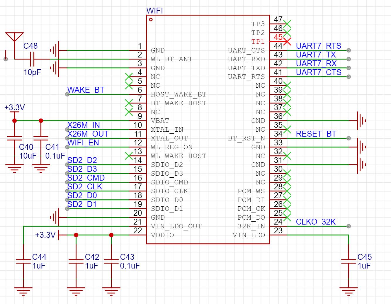
第一次用 WiFi 模块,,不太懂到底需要连哪些信号、可以不连哪些信号,,参考了 OrangePi 3B 等板子的原理图,,画图如下:
现在主要有三个疑惑:
1、BT_WAKE_HOST、WL_WAKE_HOST 是否可以不接??看名字这两个信号和唤醒有关,,那如果主机不休眠,,那是否就不需要被唤醒了?
2、天线连接是否正确,,我选的陶瓷天线,,引脚 1 通过 10pF 电容连接 AP6212 的 WL_BT_ANT 引脚,,引脚 2 悬空
3、VIN_LDO、VIN_LDO_OUT 是否可以悬空不接,,我看有些原理图上是悬空,,有些原理图上是接 10uF 电容。。
官方的产品规格书上也没有推荐的应用电路,,这些疑惑都无处可查,,哪位大神知道麻烦指点下,,谢谢。。
#34 Re: DIY/综合/Arduino/写字机/3D打印机/智能小车/平衡车/四轴飞行/MQTT/物联网 » 正点原子出逻辑分析仪了,,和DSLogic一样,也是基于 sigrok 开源解码方案。。 » 2023-07-21 17:38:58
#35 DIY/综合/Arduino/写字机/3D打印机/智能小车/平衡车/四轴飞行/MQTT/物联网 » 正点原子出逻辑分析仪了,,和DSLogic一样,也是基于 sigrok 开源解码方案。。 » 2023-07-21 11:04:39
#36 Re: DIY/综合/Arduino/写字机/3D打印机/智能小车/平衡车/四轴飞行/MQTT/物联网 » 【新玩具get】AGM AGRV2K,16.8块钱的MCU+FPGA二合一芯片 » 2023-07-10 13:55:06
#37 Re: Cortex M0/M3/M4/M7 » Keil 通过 DAPLink 连结 STM32F411 时,不发送 JTAG-to-SWD 序列。。 » 2023-07-05 19:03:02
#39 Cortex M0/M3/M4/M7 » DAPLink 连接 STM32F411 奇怪现象:接线某个 GND 时连接失败。。 » 2023-07-05 14:54:37
- XIVN1987
- 回复: 3
实验环境如下:DAPLink 是 MuseLab 的 nanoDAP v2.35,,STM32F411 测试板是 WeAct Studio 的 STM32F411CE 核心板 V3.1。
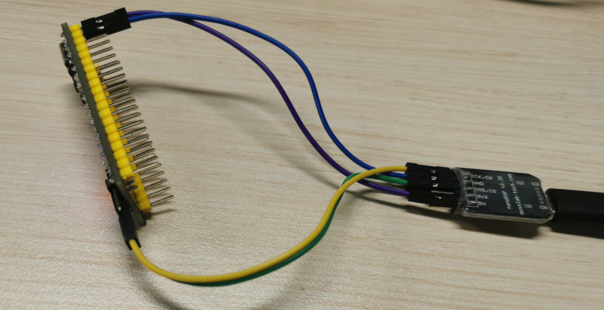
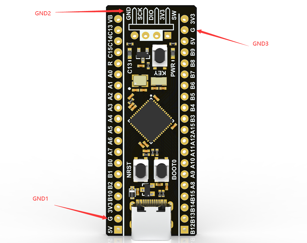
如下图,,这个板子有三个 GND,,测试发现,,当连接板子的 GND1 时,无法连接内核,,当连接板子的 GND2、GND3 时,,很容易连接内核
我测了下,,这三个 GND 之间的电阻只有 1 欧姆,,可以认为是连接良好的。。搞不懂为什么会出现这种现象,,
另外,,所还用 PyOCD 作为上位机连接过板子,,接 GND1 连接失败时报错如下:
(vexe) D:\Python38\vexe\Scripts>pyocd cmd -t stm32f412xe
0001519 E Error while initing target: Unexpected ACK value (5) returned by probe [commander]#40 Cortex M0/M3/M4/M7 » Keil 通过 DAPLink 连结 STM32F411 时,不发送 JTAG-to-SWD 序列。。 » 2023-07-04 21:44:35
- XIVN1987
- 回复: 2
如题,使用 Keil 连接芯片时失败,,通过逻辑分析仪抓 SWD 上的波形发现,,DAPLink 执行 Line reset 之后,,就直接发了 8 个 0,,然后就开始读取 IDCODE 了,,没有发送 JTAG-to-SWD 序列。。
根据网上找到的《Programming Internal Flash Over the Serial Wire Debug Interface》中如下内容,,调试器需要发送 JTAG-to-SWD 序列激活 SW-DP,,才能发送 SWD 命令。。

有两种可能导致这个问题:
1、Keil 让 DAPLink 发送 JTAG-to-SWD 序列了,,但 DAPLink 没发
2、Keil 就没让 DAPLink 发送 JTAG-to-SWD 序列
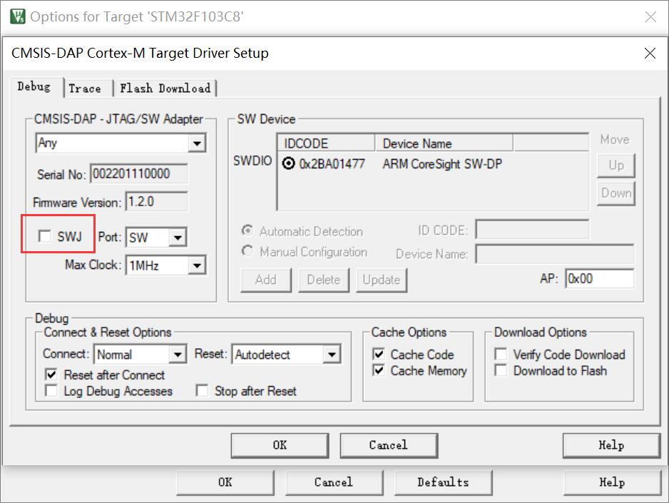
为了区分这两种情况,,我用 WireShark 抓取了一下 DAPLink 的 USB 数据,如下图所示,,结果发现 Keil 确实没让 DAPLink 发送 JTAG-to-SWD 序列。。
请问哪位大佬知道这是什么情况??是 Keil Bug 吗??我用的 Keil 版本是 5.36,,很新的版本,,感觉不应该出现这种 Bug 才对。。
最后,我上传了 WireShark 抓到的数据包,,感兴趣的大侠可以看看。。谢谢。。
WireShark_DAPLink_No_Jtag2SWD.rar
发送 Line reset: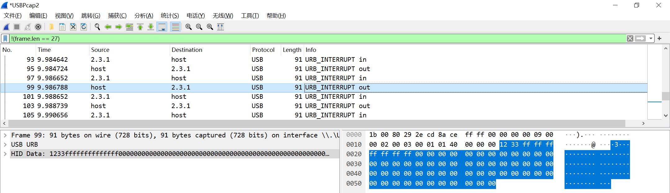
发送 8 个 0: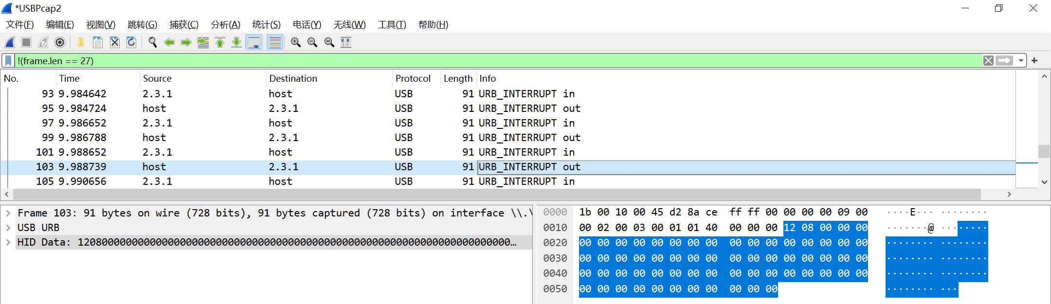
#43 Re: DIY/综合/Arduino/写字机/3D打印机/智能小车/平衡车/四轴飞行/MQTT/物联网 » 【新玩具get】AGM AGRV2K,16.8块钱的MCU+FPGA二合一芯片 » 2023-06-23 22:42:18
#44 Re: DIY/综合/Arduino/写字机/3D打印机/智能小车/平衡车/四轴飞行/MQTT/物联网 » 【新玩具get】AGM AGRV2K,16.8块钱的MCU+FPGA二合一芯片 » 2023-06-13 09:38:02
#45 Re: Cortex M0/M3/M4/M7 » DAPLink添加WINUSB支持。。 » 2023-06-01 23:02:11
#46 Re: Cortex M0/M3/M4/M7 » DAPLink添加WINUSB支持。。 » 2023-05-31 22:47:47
#47 Re: Cortex M0/M3/M4/M7 » DAPLink添加WINUSB支持。。 » 2023-05-30 19:28:14
#48 Re: Cortex M0/M3/M4/M7 » DAPLink添加WINUSB支持。。 » 2023-05-29 22:09:53
#49 Re: Cortex M0/M3/M4/M7 » DAPLink添加WINUSB支持。。 » 2023-05-26 12:00:05
@XIVN1987,大佬太牛了;ch32v305的工程编译后在307的demo板上跑了一下,好像虚拟串口用不起来,不知是什么原因,请看下
我用的测试板是自己画的,,你可以对比下看看:https://oshwhub.com/xivn1987/ch32v307
#50 Re: Cortex M0/M3/M4/M7 » DAPLink添加WINUSB支持。。 » 2023-05-26 11:57:20
#51 Re: Cortex M0/M3/M4/M7 » 国产M7来了,分享datasheet » 2023-05-12 13:46:47
XIVN1987 说:USBHS 集成了 HS PHY,,牛啊,,这点比 STM32H7 强多了
还好吧,CH32V307早都支持了
STM32H7 不支持。。
#52 Re: Cortex M0/M3/M4/M7 » 国产M7来了,分享datasheet » 2023-05-11 21:48:50

#53 Re: PikaPython(嵌入式Python引擎) » 我希望在python中直接访问C语言的全局变量,直接通个python修改或者读取变量,而不通过方法,有什么办法可以实现吗? » 2023-04-21 09:37:53
https://docs.python.org/3/library/ctypes.html#accessing-values-exported-from-dlls
Accessing values exported from dlls
Some shared libraries not only export functions, they also export variables. An example in the Python library itself is the Py_OptimizeFlag, an integer set to 0, 1, or 2, depending on the -O or -OO flag given on startup.
ctypes can access values like this with the in_dll() class methods of the type. pythonapi is a predefined symbol giving access to the Python C api:
opt_flag = c_int.in_dll(pythonapi, "Py_OptimizeFlag")
print(opt_flag)
c_long(0)#55 Re: 全志 SOC » spi nand flash有什么优点和缺点呢? » 2023-03-23 17:37:34
#56 Re: 全志 SOC » spi nand flash有什么优点和缺点呢? » 2023-03-23 11:37:42
刚刚看到一个磨损均衡的库:https://github.com/azure-rtos/levelx
所以说,,磨损均衡还是挺复杂的,,
#57 Re: 全志 SOC » spi nand flash有什么优点和缺点呢? » 2023-03-23 11:34:07
#59 Re: Cortex M0/M3/M4/M7 » 求个推荐,内置高速USB(速度480 Mb/s)PHY的单片机 » 2023-02-10 10:04:56
CH32V305 主频 144MHz、128KB Flash、32KB RAM、TSSOP20 封装、内置 HSUSB PHY、价格 10 块左右,,完美符合楼主的需求了。。
虽然不是 Cortex-M 内核,,但 RISC-V 也不是冷门内核,,现在用的厂家越来越多了,,比如知名WiFi SoC厂商乐鑫之前用的Xtensa ISA,现在出的芯片大多是RISC-V内核的了(ESP32-C2/3/5/6、H2、P4)
前段儿时间用 CH32V305 移植了下 DAPLink (https://github.com/XIVN1987/DAPLink),,用起来感觉和 STM32 那些差别也不大(毕竟都是用 C 语言编程,,又不需要手写汇编),,MounRiver Studio 用起来也还行,,跟 Keil 相比各有长短吧。。
#60 Re: RISC-V » CH32V系列非0等待区使用及简陋的性能测试 » 2023-01-30 15:31:00
#63 Re: Cortex M0/M3/M4/M7 » Tiny-DAPLink:开源CH552实现的CMSIS-DAP v2升级版 » 2023-01-26 22:05:26
CH32V203F8 3块钱,可以跑到 144MHz,也支持 crystall-less USB。。
如果不想用 RISC-V 的话,,AT32F425F8 3.75元,Cortex-M4 内核,96MHz,,同样支持 crystall-less USB。。
原理图 & PCB:https://oshwhub.com/xivn1987/daplink
源代码:https://github.com/XIVN1987/DAPLink
#64 Re: Cortex M0/M3/M4/M7 » DAPLink添加WINUSB支持。。 » 2023-01-20 21:07:21
#65 Re: Cortex M0/M3/M4/M7 » DAPLink添加WINUSB支持。。 » 2023-01-12 21:55:11
#66 Re: RISC-V » RISC-V不支持非对齐地址访问非常坑 » 2023-01-05 18:12:20

#67 Re: RISC-V » RISC-V不支持非对齐地址访问非常坑 » 2023-01-05 18:08:31
#69 Re: RISC-V » 最权威的 RISC-V 汇编程序员手册 » 2022-11-24 19:16:09
#70 Re: RISC-V » 开源一个AB32VG1的开发板 » 2022-11-24 16:37:45
#71 Re: RISC-V » 国产riscv芯片汇总 » 2022-11-14 11:42:39

#72 Re: RISC-V » CH32V307内置SPI FLASH来自普冉 » 2022-11-13 15:50:53
#73 Re: RISC-V » 国产riscv芯片汇总 » 2022-11-10 16:09:06
#74 Re: RISC-V » RISC-V核心的SoC有没有已经在产品上广泛使用的型号? » 2022-11-08 20:39:54
#75 Re: RISC-V » RISC-V核心的SoC有没有已经在产品上广泛使用的型号? » 2022-11-08 16:22:30

#76 Re: RISC-V » RISC-V核心的SoC有没有已经在产品上广泛使用的型号? » 2022-11-08 09:30:24
#77 Re: RISC-V » 博流智能将要推出杀手级芯片bl808(可以跑linux) » 2022-11-03 10:16:28
#78 Re: DIY/综合/Arduino/写字机/3D打印机/智能小车/平衡车/四轴飞行/MQTT/物联网 » TinyUSer,极致体积的USB转串口小板,基于沁恒CH340X » 2022-11-02 10:25:33
#79 Re: RISC-V » 博流智能将要推出杀手级芯片bl808(可以跑linux) » 2022-10-27 20:59:45
#81 Re: RISC-V » WCH又搞了个性价比王炸CH32V003 » 2022-10-17 11:26:17
#82 Re: VMWare/Linux/Ubuntu/Fedora/CentOS/U-BOOT » 辣鸡向日葵,花了9元买了一个月的会员,却什么都干不了。我现在自己动手,用FRP这个优秀的开源软件把内网穿透搭起来了 » 2022-09-19 09:41:46
#83 Re: VMWare/Linux/Ubuntu/Fedora/CentOS/U-BOOT » R5S 运行 Debian 配置成软路由,NAT 不工作,,求教怎么改。。 » 2022-09-18 21:49:01
问题解决了,,解决方法是在 /etc/dhcp/dhcpd.conf 中下面的 subnet 配置中添加 routers 和 domain-name-servers 设置
subnet 192.168.2.0 netmask 255.255.255.0 {
 range 192.168.2.10 192.168.2.250;
 option routers 192.168.2.1;
 option domain-name-servers 8.8.8.8;
}
routers 选项用来设置接入设备的默认网关,这样接入设备就能 ping 通外网 IP 了。。
domain-name-servers 选项用来设置接入设备的域名解析服务器,之前由于笔记本通过 WiFi 获取的 DNS 是主路由的 IP,因此我也将上面的 DNS 设置成了 br-lan 的 IP,,结果发现不能 ping 通域名,,改成 8.8.8.8 就可以了。。
#84 Re: VMWare/Linux/Ubuntu/Fedora/CentOS/U-BOOT » R5S 运行 Debian 配置成软路由,NAT 不工作,,求教怎么改。。 » 2022-09-18 15:24:40
补充,,iptable 规则如下:
root@Armbian:~# iptables -nvL
Chain INPUT (policy ACCEPT 0 packets, 0 bytes)
 pkts bytes target     prot opt in     out     source               destination

Chain FORWARD (policy ACCEPT 0 packets, 0 bytes)
 pkts bytes target     prot opt in     out     source               destination
    0     0 ACCEPT     all  --  br-lan wifi0   0.0.0.0/0            0.0.0.0/0
    0     0 ACCEPT     all  --  wifi0  br-lan  0.0.0.0/0            0.0.0.0/0            ctstate RELATED,ESTABLISHED

Chain OUTPUT (policy ACCEPT 0 packets, 0 bytes)
 pkts bytes target     prot opt in     out     source               destination

root@Armbian:~# iptables -t nat -nvL
Chain PREROUTING (policy ACCEPT 0 packets, 0 bytes)
 pkts bytes target     prot opt in     out     source               destination

Chain INPUT (policy ACCEPT 0 packets, 0 bytes)
 pkts bytes target     prot opt in     out     source               destination

Chain POSTROUTING (policy ACCEPT 0 packets, 0 bytes)
 pkts bytes target     prot opt in     out     source               destination
    0     0 MASQUERADE  all  --  *      wifi0   0.0.0.0/0            0.0.0.0/0

Chain OUTPUT (policy ACCEPT 0 packets, 0 bytes)
pkts bytes target prot opt in out source destination#85 Re: VMWare/Linux/Ubuntu/Fedora/CentOS/U-BOOT » R5S 运行 Debian 配置成软路由,NAT 不工作,,求教怎么改。。 » 2022-09-18 11:24:35
执行 ipconfig /all 打印如下,,看起来设置都正常的,,没发现什么问题
无线局域网适配器 WLAN 3:

   连接特定的 DNS 后缀 . . . . . . . : lan
   描述. . . . . . . . . . . . . . . : Intel(R) Wi-Fi 6 AX200 160MHz
   物理地址. . . . . . . . . . . . . : 64-BC-58-05-05-9B
   DHCP 已启用 . . . . . . . . . . . : 是
   自动配置已启用. . . . . . . . . . : 是
   IPv6 地址 . . . . . . . . . . . . : fd88:88b7:3d35:0:6584:d263:af42:295e(首选)
   临时 IPv6 地址. . . . . . . . . . : fd88:88b7:3d35:0:a5a8:3e7b:b0f4:5beb(首选)
   本地链接 IPv6 地址. . . . . . . . : fe80::6584:d263:af42:295e%11(首选)
   IPv4 地址 . . . . . . . . . . . . : 192.168.18.107(首选)
   子网掩码  . . . . . . . . . . . . : 255.255.255.0
   获得租约的时间  . . . . . . . . . : 2022年9月18日 6:28:28
   租约过期的时间  . . . . . . . . . : 2022年9月18日 23:16:11
   默认网关. . . . . . . . . . . . . : 192.168.18.1
   DHCP 服务器 . . . . . . . . . . . : 192.168.18.1
   DHCPv6 IAID . . . . . . . . . . . : 577027160
   DHCPv6 客户端 DUID  . . . . . . . : 00-01-00-01-28-4B-DA-A9-80-30-49-2D-36-C5
   DNS 服务器  . . . . . . . . . . . : 192.168.18.1
   TCPIP 上的 NetBIOS  . . . . . . . : 已启用
   连接特定的 DNS 后缀搜索列表:
                                       lan

以太网适配器 以太网 3:

   连接特定的 DNS 后缀 . . . . . . . : example.org
   描述. . . . . . . . . . . . . . . : ASIX AX88179A USB 3.2 Gen1 to Gigabit Ethernet Adapter
   物理地址. . . . . . . . . . . . . : F8-E4-3B-5B-2C-46
   DHCP 已启用 . . . . . . . . . . . : 是
   自动配置已启用. . . . . . . . . . : 是
   本地链接 IPv6 地址. . . . . . . . : fe80::f474:2cd3:a8c:c01e%19(首选)
   IPv4 地址 . . . . . . . . . . . . : 192.168.2.10(首选)
   子网掩码  . . . . . . . . . . . . : 255.255.255.0
   获得租约的时间  . . . . . . . . . : 2022年9月18日 11:12:34
   租约过期的时间  . . . . . . . . . : 2022年9月18日 11:27:27
   默认网关. . . . . . . . . . . . . : 192.168.2.1
   DHCP 服务器 . . . . . . . . . . . : 192.168.2.1
   DHCPv6 IAID . . . . . . . . . . . : 922281019
   DHCPv6 客户端 DUID  . . . . . . . : 00-01-00-01-28-4B-DA-A9-80-30-49-2D-36-C5
   DNS 服务器  . . . . . . . . . . . : 192.168.2.1
   TCPIP 上的 NetBIOS  . . . . . . . : 已启用
ip、gateway、dns 服务器都设置了,,可笔记本只连 r5s lan 口的时候就是无法 ping 通外网,,不知道还有哪里设置不对。。
#86 VMWare/Linux/Ubuntu/Fedora/CentOS/U-BOOT » R5S 运行 Debian 配置成软路由,NAT 不工作,,求教怎么改。。 » 2022-09-18 00:59:24
- XIVN1987
- 回复: 4
/etc/network/interfaces 配置如下:
auto eth0
iface eth0 inet dhcp

auto wifi0
iface wifi0 inet dhcp
    wpa-essid xxxxxxxxxx
    wpa-psk xxxxxxxxxx

auto br-lan
iface br-lan inet static
    address 192.168.2.1
    network 192.168.2.0
    netmask 255.255.255.0
    broadcast 192.168.2.255
    bridge-ports eth1 eth2
R5S 通过 USB WiFi 连接主路由,,配置 dhcpd 监听网桥 br-lan,,笔记本通过网线连接 R5S LAN 口
这样配置后,,R5S 通过 WiFi 联通互联网成功,,笔记本分配局域网地址成功,,
接下来只需要配置好 NAT,,笔记本应该就能通过 R5S 联通互联网了,,根据网上搜到的资料,NAT 配置代码如下:
EXTIF="wifi0"
INTIF="br-lan"

echo 1 > /proc/sys/net/ipv4/ip_forward

iptables -t nat --flush
iptables -t filter --flush

iptables -t nat -A POSTROUTING -o "$EXTIF" -j MASQUERADE

# Allow traffic from internal to external
iptables -A FORWARD -i "$INTIF" -o "$EXTIF" -j ACCEPT
# Allow returning traffic from external to internal
iptables -A FORWARD -i "$EXTIF" -o "$INTIF" -m conntrack --ctstate ESTABLISHED,RELATED -j ACCEPT
但我执行上述代码后,,笔记本以太网显示“无 Internet”,,笔记本上 ping 192.168.2.1 能 ping 通,,但 ping 192.168.18.1(主路由器IP)ping 不通,,请教我哪里配置有问题?该怎么解决??多谢大侠指教。。
#92 Re: GM8135s/GM8136s/GM8135/GM8136/GM8125/GM8126 » GM8135S还在正常出货吗?或者还有其他类似的吗? » 2022-08-17 13:55:31
#93 Re: 全志 SOC » 使用rust对arm9处理器进行裸机开发 » 2022-07-08 10:28:10
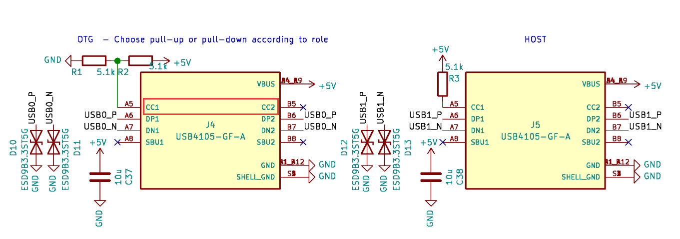
#94 Re: 全志 SOC » USB Type-C 如何实现 OTG? » 2022-06-24 13:36:01
#95 Re: 全志 SOC » USB Type-C 如何实现 OTG? » 2022-06-24 13:15:11
#96 Re: 全志 SOC » USB Type-C 如何实现 OTG? » 2022-06-24 12:59:51
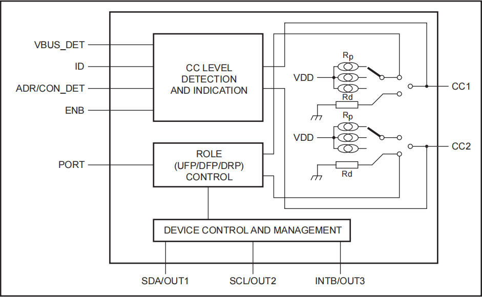
基本搞清楚了,,好像是需要使用专门的芯片才能实现,比如NXP的 PTN5150
基本原理猜测是:上电 CC1/CC2 引脚悬空,当主机接入时,CC1/CC2 会被主机端上拉电阻拉高;从从机接入时,CC1/CC2 会被从机端下拉电阻拉低,这样就能检测到连接,并能区分出对方是主机还是从机。
区分出以后,若对方是主机,则 PTN5150 将 CC1/CC2 下拉,将自己配置成从机;若对方是从机,则 PTN5150 将 CC1/CC2 上拉,将自己配置成主机。完成主从连接。
另外,这个芯片还通过 ID 引脚输出自己主从模式,传统的 USB 2.0 OTG 的 ID 脚可连接此引脚,得知 PTN5150 的检测结果。
#98 Re: RISC-V » 性能最强的 RISC-V 内核单片机:HPM6750 » 2022-05-13 20:06:44
#99 Re: RISC-V » 性能最强的 RISC-V 内核单片机:HPM6750 » 2022-05-13 18:08:42
#100 Re: RISC-V » 性能最强的 RISC-V 内核单片机:HPM6750 » 2022-05-11 11:16:14
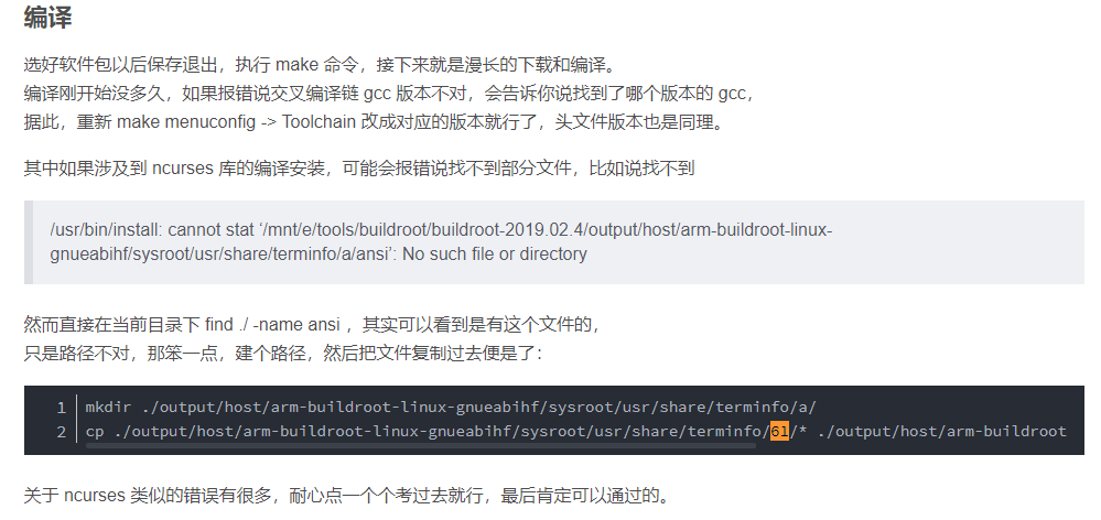
#101 Re: RK3288/RK3399/RK1108 » WSL下编译buildroot,sysroot/usr/share/terminfo 下的目录名都是 ASCII 码,请问怎么解决? » 2022-05-11 11:02:44
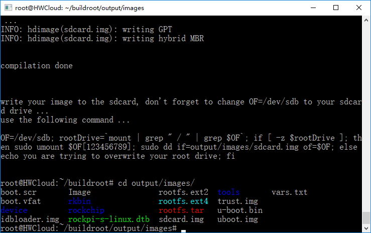
编译完成了,,成功生成了 sdcard.img,,
没有遇到其他网友说的需要“用fakeroot-tcp替换fakeroot-sysv”的问题
过程还算顺利,,就遇到两个问题,,除了楼上那个问题,,另一个是 WSL 中 Ubuntu 的 PATH 会包含 Windows 的 PATH,,而 Windows 的 PATH 路径可能包含空格,,导致编译出错,,解放方法是使用 “PATH=/usr/local/sbin:/usr/local/bin:/usr/sbin:/usr/bin:/sbin:/bin make” 临时覆盖 PATH
看起来 WSL 下编译 Buildroot 还是可行的。。
#102 Re: RISC-V » 性能最强的 RISC-V 内核单片机:HPM6750 » 2022-05-11 10:04:53
#104 Re: RISC-V » 与 ARM 相比,Risc-V 有多好? » 2022-05-11 09:49:03
#105 Re: 全志 SOC » YuzukiCK1N - 基于全志V3x的触屏小电脑【开源硬件】 » 2022-05-11 09:15:54
#106 Re: RK3288/RK3399/RK1108 » WSL下编译buildroot,sysroot/usr/share/terminfo 下的目录名都是 ASCII 码,请问怎么解决? » 2022-05-11 00:37:35
还没有找到目录名变成数字的根源,暂时想到一个方法避免手动拷贝,,先走通编译流程吧
找到 buildroot\package\ncurses\ncurses.mk 中如下内容:
define NCURSES_TARGET_CLEANUP_TERMINFO
	$(RM) -rf $(TARGET_DIR)/usr/share/terminfo $(TARGET_DIR)/usr/share/tabset
	$(foreach t,$(NCURSES_TERMINFO_FILES), \
		$(INSTALL) -D -m 0644 $(STAGING_DIR)/usr/share/terminfo/$(t) \
			$(TARGET_DIR)/usr/share/terminfo/$(t)
	)
endef
可知,第一个 $(t) 指定源地址,第二个 $(t) 指定目的地址,只需要将第一个 $(t) 的第一个字符转换成其 ASCII 码数字应该就可以编译了
不懂 shell 怎么处理字符串,,用 python 处理,改成如下内容:
define NCURSES_TARGET_CLEANUP_TERMINFO
	$(RM) -rf $(TARGET_DIR)/usr/share/terminfo $(TARGET_DIR)/usr/share/tabset
	$(foreach t,$(NCURSES_TERMINFO_FILES), \
		$(INSTALL) -D -m 0644 $(STAGING_DIR)/usr/share/terminfo/$(shell python3 -c \
			"import sys; t = sys.argv[1]; t = f'{ord(t[0]):x}{t[1:]}'; print(t)" ${t}) \
			$(TARGET_DIR)/usr/share/terminfo/$(t)
	)
endef#107 Re: RK3288/RK3399/RK1108 » WSL下编译buildroot,sysroot/usr/share/terminfo 下的目录名都是 ASCII 码,请问怎么解决? » 2022-05-09 14:52:53
#108 Re: RK3288/RK3399/RK1108 » WSL下编译buildroot,sysroot/usr/share/terminfo 下的目录名都是 ASCII 码,请问怎么解决? » 2022-05-09 14:45:43
我现在想到的一个可能有效的办法是,修改 buildroot\package\ncurses\ncurses.mk 下的如下部分:
NCURSES_TERMINFO_FILES = \
	a/ansi \
	d/dumb \
	l/linux \
	p/putty \
	p/putty-256color \
	p/putty-vt100 \
	s/screen \
	s/screen-256color \
	v/vt100 \
	v/vt100-putty \
	v/vt102 \
	v/vt200 \
	v/vt220 \
	x/xterm \
	x/xterm+256color \
	x/xterm-256color \
	x/xterm-color \
	x/xterm-xfree86 \
	$(call qstrip,$(BR2_PACKAGE_NCURSES_ADDITIONAL_TERMINFO))
把其中的 a、d、l、p、s、v、x 等目录名改成其对应的 ASCII 码。。
但是我更想知道目录名是怎么变成 ASCII 码的,,在对应的位置修改,不让它变成 ASCII 码
#109 RK3288/RK3399/RK1108 » WSL下编译buildroot,sysroot/usr/share/terminfo 下的目录名都是 ASCII 码,请问怎么解决? » 2022-05-09 14:40:53
- XIVN1987
- 回复: 4
编译报错:
/usr/bin/install -D -m 0644 /mnt/d/Program/Ubuntu/buildroot/output/host/aarch64-buildroot-linux-uclibc/sysroot/usr/share/terminfo/a/ansi /mnt/d/Program/Ubuntu/buildroot/output/target/usr/share/terminfo/a/ansi
/usr/bin/install: cannot stat '/mnt/d/Program/Ubuntu/buildroot/output/host/aarch64-buildroot-linux-uclibc/sysroot/usr/share/terminfo/a/ansi': No such file or directory
查看 sysroot/usr/share/terminfo 下内容如下:
root@wmxpc:~/win/buildroot# ls /mnt/d/Program/Ubuntu/buildroot/output/host/aarch64-buildroot-linux-uclibc/sysroot/usr/share/terminfo/
31  34  37  41  4d  51  62  65  68  6b  6e  71  74  77
32  35  38  45  4e  58  63  66  69  6c  6f  72  75  78
33  36  39  4c  50  61  64  67  6a  6d  70  73  76  7a
似乎是把目录名 a 变成了它的 ASCII 码 61,,
请问这是什么导致的??怎么解决?
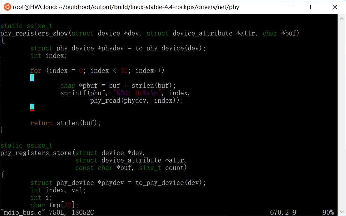
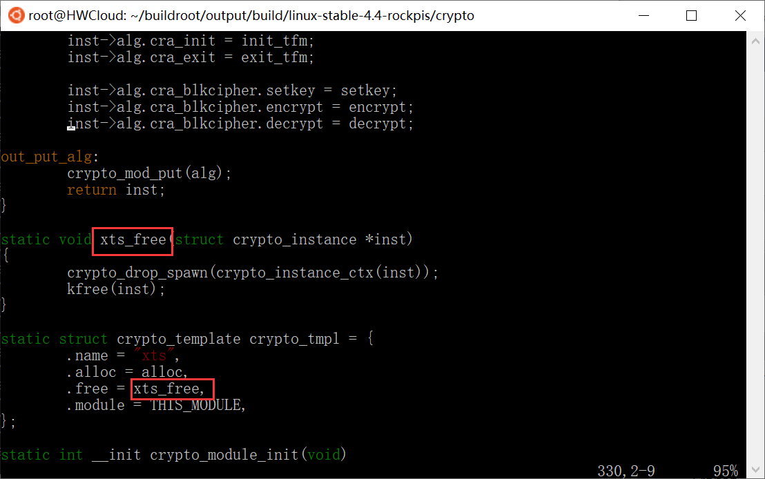
#114 Re: RK3288/RK3399/RK1108 » host-fakeroot patch出错,哪位大神知道怎么解决,,谢谢 » 2022-02-17 21:07:02
大概搞清楚了,,
buildroot/package/fakeroot/0002-libfakeroot.c-define-_STAT_VER-if-not-already-define.patch
和
buildroot.rockchip/patches.rockpis/fakeroot/0002.stat_ver.patch
中都有如下内容:
diff --git a/libfakeroot.c b/libfakeroot.c
index 3e80e38..14cdbc4 100644
--- a/libfakeroot.c
+++ b/libfakeroot.c
@@ -90,6 +90,16 @@
 #define SEND_GET_XATTR64(a,b,c) send_get_xattr64(a,b)
 #endif

+#ifndef _STAT_VER
+ #if defined (__aarch64__)
+  #define _STAT_VER 0
+ #elif defined (__x86_64__)
+  #define _STAT_VER 1
+ #else
+  #define _STAT_VER 3
+ #endif
+#endif
+
对同一位置完全相同的补丁,前一个打上,后一个肯定就打不上了,,删掉其中一个补丁就可以了
#115 RK3288/RK3399/RK1108 » host-fakeroot patch出错,哪位大神知道怎么解决,,谢谢 » 2022-02-17 12:15:30
- XIVN1987
- 回复: 2
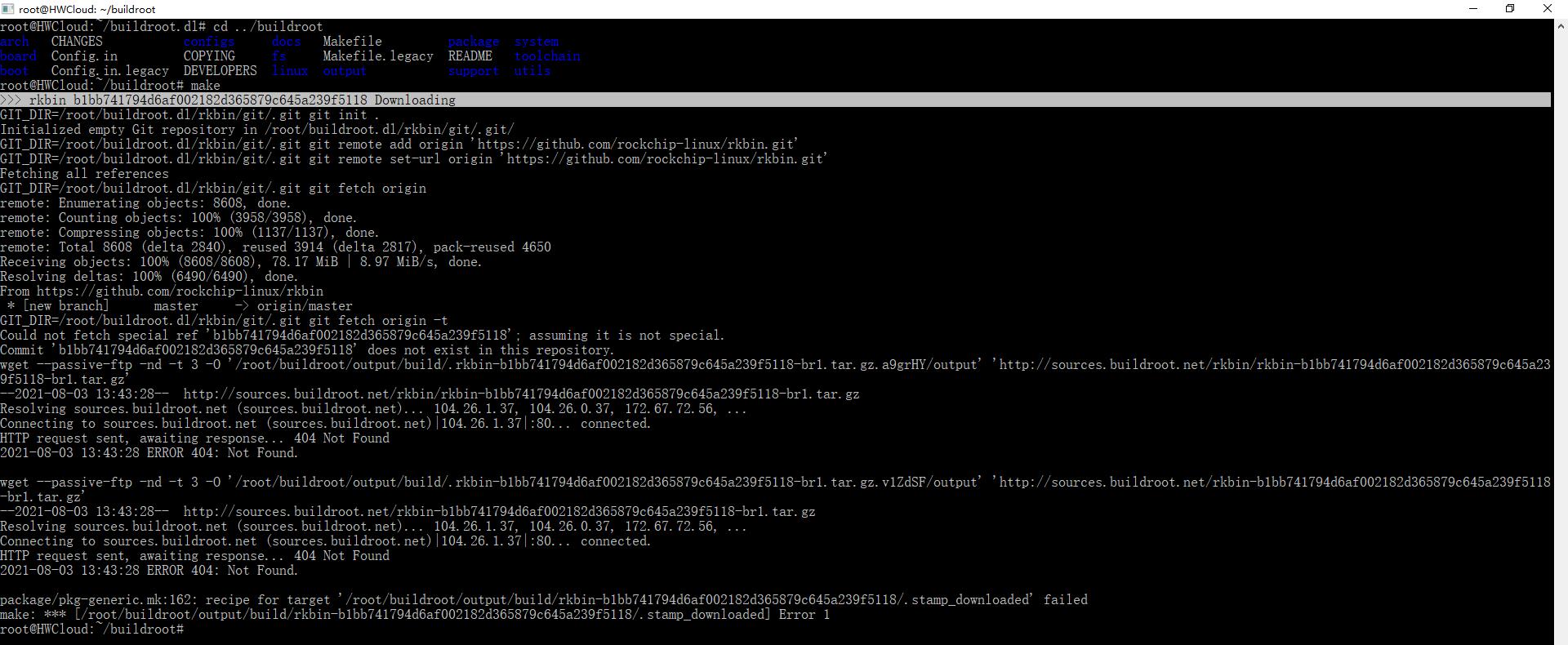
编译命令如下:
git clone https://github.com/buildroot/buildroot.git
git clone https://github.com/flatmax/buildroot.rockchip.git
cd buildroot
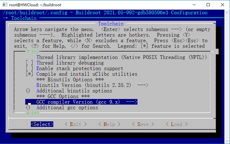
make BR2_EXTERNAL=../buildroot.rockchip rockpis_defconfig
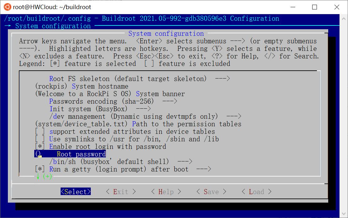
make menuconfig
# Toolchain 下 GCC compiler Version 由 gcc 10.x 改为 gcc 9.x
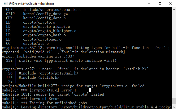
make报错信息如下:
fakeroot_1.25.3.orig.tar.gz: OK (sha256: 8e903683357f7f5bcc31b879fd743391ad47691d4be33d24a76be3b6c21e956c)
>>> host-fakeroot 1.25.3 Extracting
gzip -d -c /root/buildroot.dl/fakeroot/fakeroot_1.25.3.orig.tar.gz | tar --strip-components=1 -C /root/buildroot/output/build/host-fakeroot-1.25.3   -xf -
>>> host-fakeroot 1.25.3 Patching

Applying 0001-skip-doc-subdirs.patch using patch:
patching file doc/Makefile.am

Applying 0002-libfakeroot.c-define-_STAT_VER-if-not-already-define.patch using patch:
patching file libfakeroot.c

Applying 0003-libfakeroot.c-add-wrappers-for-new-glibc-2.33-symbol.patch using patch:
patching file libfakeroot.c

Applying 0004-configure.ac-fix-__xmknod-at-pointer-argument.patch using patch:
patching file configure.ac

Applying 0005-fix-build-regression-on-macOS.patch using patch:
patching file configure.ac
patching file libfakeroot.c

Applying 0002.stat_ver.patch using patch:
patching file libfakeroot.c
Reversed (or previously applied) patch detected!  Skipping patch.
1 out of 1 hunk ignored -- saving rejects to file libfakeroot.c.rej
patching file libfakeroot.c
Hunk #1 succeeded at 1402 with fuzz 1 (offset 50 lines).
patching file libfakeroot.c
Hunk #1 succeeded at 2575 (offset 50 lines).
patching file configure.ac
Reversed (or previously applied) patch detected!  Skipping patch.
2 out of 2 hunks ignored -- saving rejects to file configure.ac.rej
patching file libfakeroot.c
Hunk #1 succeeded at 2116 (offset 50 lines).
Hunk #2 succeeded at 2135 (offset 50 lines).
patching file configure.ac
patching file libfakeroot.c
Hunk #4 succeeded at 2035 (offset 50 lines).
Hunk #5 succeeded at 2636 (offset 50 lines).
patching file wrapawk_macosx
patching file wrapfunc.inp
make: *** [package/pkg-generic.mk:227: /root/buildroot/output/build/host-fakeroot-1.25.3/.stamp_patched] Error 1
#117 Re: Php/Nodejs/Web/HTML5/Javascript/微信开发/Python » Pyinstaller打包使用pyusb的python程序 » 2022-01-19 10:55:58
#118 Php/Nodejs/Web/HTML5/Javascript/微信开发/Python » Pyinstaller打包使用pyusb的python程序 » 2022-01-18 10:24:40
- XIVN1987
- 回复: 2
用Python写了个使用pyusb库的模仿JLink Commander的应用:https://github.com/XIVN1987/DAPCmdr
为了方便同事使用,于是用“pyinstaller -F path/to/DAPCmdr.py”将其打包成单个exe可执行文件,,
可是打包后程序执行报错“No backend available”,,无法发现和连接DAPLink,,根据之前调试pyusb的经验,,这是pyusb库找不到libusb.dll导致的
可是源码形式下可以找到libusb.dll,,为啥打包后就不行了呢??经过搜索和阅读源码发现,,原来pyinstaller修改了pyusb搜索libusb.dll的方式。。
pyusb原本的libusb.dll搜索代码执行流程如下:
_load_library() # usb\backend\libusb1.py
    usb.libloader.load_locate_library('libusb-1.0')

load_locate_library(name) # usb\libloader.py
    ctypes.util.find_library(name + '.dll')

find_library(name) # ctypes\util.py
    for directory in os.environ['PATH'].split(os.pathsep):
        fname = os.path.join(directory, name)
        if os.path.isfile(fname):
            return fname
简单来说pyusb最终是通过ctypes.util.find_library搜索libusb.dll的,,而ctypes.util.find_library是在环境变量PATH包含的路径下搜索libusb.dll的,,
我为了不修改系统变量PATH依然能够执行DAPCmdr.py,所以在DAPCmdr.py的起始处添加了下面一行代码:
os.environ['PATH'] = os.path.join(os.path.dirname(os.path.abspath(__file__)), 'libusb-1.0.24/MinGW64/dll') + os.pathsep + os.environ['PATH']也就是把DAPCmdr.py所在目录下的 libusb-1.0.24/MinGW64/dll 目录路径加入环境变量 PATH,这样 ctypes.util.find_library 就能从 DAPCmdr.py 所在路径下搜索到 libusb.dll,而且不管 DAPCmdr 目录拷贝到哪里,DAPCmdr.py 都能正常启动执行。。
而 Pyinstaller 打包使用 pyusb 库的程序时,会用到 site-packages\\_pyinstaller_hooks_contrib\\hooks\\rthooks\\pyi_rth_usb.py 文件,其内容如下:
def get_load_func(type, candidates):
    def _load_library(find_library=None):
        exec_path = sys._MEIPASS

        l = None
        for candidate in candidates:
            # Do linker's path lookup work to force load bundled copy.
            if sys.platform == 'win32' or sys.platform == 'cygwin':
                libs = glob.glob("%s\\%s*.dll" % (exec_path, candidate))
            else:
                libs = glob.glob("%s/%s*.so*" % (exec_path, candidate))
            for libname in libs:
                try:
                    l = ctypes.WinDLL(libname)
                    if l is not None:
                        break
                except:
                    l = None
            if l is not None:
                break
        else:
            raise OSError('USB library could not be found')

        return l
    return _load_library


import usb.backend.libusb1 as libusb10
libusb10._load_library = get_load_func('libusb10', ('usb-1.0', 'libusb-1.0', 'usb'))
可以看到,它用自己编写的 _load_library 函数替代了usb.backend.libusb1 自身的 _load_library 函数,,而它自己编写的 _load_library 是在打包生成的 DAPCmdr.exe 文件所在的目录下查找 libusb.dll 的。。
所以我按照源码目录结构把 libusb-1.0.24 文件夹拷贝到 DAPCmdr.exe 所在目录,,DAPCmdr.exe 执行时是无法搜索到 libusb.dll 的。。只有将 libusb-1.0.24 文件夹下的 libusb-1.0.dll 文件拷贝到 DAPCmdr.exe 所在目录,,DAPCmdr.exe 执行时才能搜索到 libusb.dll
#119 Re: Cortex M0/M3/M4/M7 » DAPLink添加WINUSB支持。。 » 2022-01-14 09:24:51
#120 Re: 全志 SOC » 开源D1s核心板+底板 » 2022-01-13 09:05:14
#121 Re: Cortex M0/M3/M4/M7 » DAPLink添加WINUSB支持。。 » 2022-01-12 22:08:22
DAPCmdr、MCUProg、RTTView三件套添加CMSIS-DAP v2支持,,感兴趣的可以mark下 ![]()
https://github.com/XIVN1987/DAPCmdr
https://github.com/XIVN1987/MCUProg
https://github.com/XIVN1987/RTTView
#122 Cortex M0/M3/M4/M7 » DAPLink添加WINUSB支持。。 » 2022-01-12 20:55:19
- XIVN1987
- 回复: 24
之前使用HID传输协议,下载速度比较慢,,所以升级添加了 WINUSB 协议支持,,
通过在Keil Option窗口C/C++页是否定义 DAP_FW_V1 宏,选择使用 HID 协议还是 WINUSB 协议。。
官方的 DAPLink 功能更多,,但代码也很多,,不易阅读,,我这个移植代码比较简洁,,容易读懂和移植,,感兴趣的可以看下
#123 Re: Cortex M0/M3/M4/M7 » 一个GD32的CAN外设硬件bug » 2022-01-05 17:35:06
#124 Re: Cortex M0/M3/M4/M7 » 一个GD32的CAN外设硬件bug » 2022-01-04 21:20:46
#125 Re: Cortex M0/M3/M4/M7 » DAPLink添加软件复位功能。。 » 2021-12-27 10:22:08
#126 Re: Cortex M0/M3/M4/M7 » DAPLink添加软件复位功能。。 » 2021-12-27 09:31:15
#127 Re: Cortex M0/M3/M4/M7 » DAPLink添加软件复位功能。。 » 2021-12-26 12:17:59
#128 Re: Cortex M0/M3/M4/M7 » DAPLink添加软件复位功能。。 » 2021-12-25 19:52:38
#129 Cortex M0/M3/M4/M7 » DAPLink添加软件复位功能。。 » 2021-12-25 18:54:24
- XIVN1987
- 回复: 14
最近使用DAPLink,发现即使在Keil下载设置中勾选了“Reset and Run”,下载后仍然不能自动复位执行,,需要手动按一下复位按键程序才能执行,,感觉比较麻烦。。所以就打算给DAPLink添加软件复位功能。。
查看DAPLink源码发现其中有 ID_DAP_ResetTarget 命令,该命令最终调用函数 RESET_TARGET,感觉只要在该函数中实现通过 SWD 向目标芯片的 SCB->AIRCR 寄存器写入复位请求即可实现复位目标芯片的功能,,代码如下:
extern uint8_t swd_write_word(uint32_t addr, uint32_t val);
static uint32_t RESET_TARGET(void)
{
	swd_write_word((uint32_t)&SCB->AIRCR, ((0x5FA << SCB_AIRCR_VECTKEY_Pos) | SCB_AIRCR_SYSRESETREQ_Msk));

    return 1;	// change to '1' when a device reset sequence is implemented
}
可是修改后发现,并不管用,,目标板并没有复位。。
通过Wireshark抓取Keil与DAPLink的通信过程发现,Keil并没有发送 ID_DAP_ResetTarget 命令,,而是通过 ID_DAP_SWJ_Pins 命令直接通过JTAG的nRESET引脚复位目标芯片。。可是我的DAPLink上没有nRESET引脚,,所以我在DAPLink响应 ID_DAP_SWJ_Pins 命令拉低 nRESET 引脚时执行 SCB->AIRCR 写入操作,,代码如下:
extern uint8_t swd_write_word(uint32_t addr, uint32_t val);
static __inline void PIN_nRESET_OUT(uint32_t bit)
{
	if(bit == 0)
	{
		swd_write_word((uint32_t)&SCB->AIRCR, ((0x5FA << SCB_AIRCR_VECTKEY_Pos) | SCB_AIRCR_SYSRESETREQ_Msk));
	}
}
这样,,不需要接nRESET引脚,,SWD下载后也能自动复位执行了。。
代码工程已经更新到github上,,感兴趣的可以看下:https://github.com/XIVN1987/DAPLink
#130 Re: 全志 SOC » 开源个D1s核心板 » 2021-12-24 21:23:15
#131 Re: 全志 SOC » 开源个D1s核心板 » 2021-12-24 21:20:55
#136 Re: Cortex M0/M3/M4/M7 » 分享我画的M482简易开发板,板载DAPLink! » 2021-12-19 00:22:27
问下楼主,DAPLink的烧录速度如何?我试了nu-link + OpenOCD的烧录速度太慢了才4KB/S,对比ST-Link还真不习惯。
实测如下:文件大小 426KB,总共耗时 21s,其中打印2000012D是在执行擦除,打印2000038D是在执行写入,,擦除和写入分别耗时10s,因此写入速度大概是40KB/s。。
我这个DAPLink是用的HID传输协议,全速模式下HID速度最高也就64B*1000/1024=62.5KB/s,考虑到待烧写数据传输到DAPLink后还需要通过SWD接口发送到目标芯片、目标芯片Flash写入也需要耗时,,因此40KB/s估计就是全速USB HID方案的烧写速度极限了。。
要想再快就只能使用CMSIS-DAP v2的WINUSB传输协议了,,采用这个协议理论上能够做到和J-Link、ST-Link一样快。。
另外,,关于擦除时间的问题,,感觉耗时比较长,,于是查了下
擦除1个页大概100ms,,426KB对应106个Flash页,,总共耗时100ms*106=10s,,和实测结果差不多
上面用到的烧录软件,感兴趣可以下载试试:https://github.com/XIVN1987/MCUProg
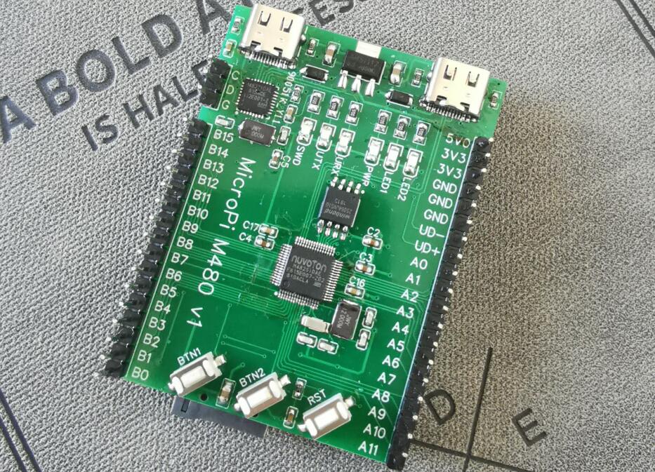
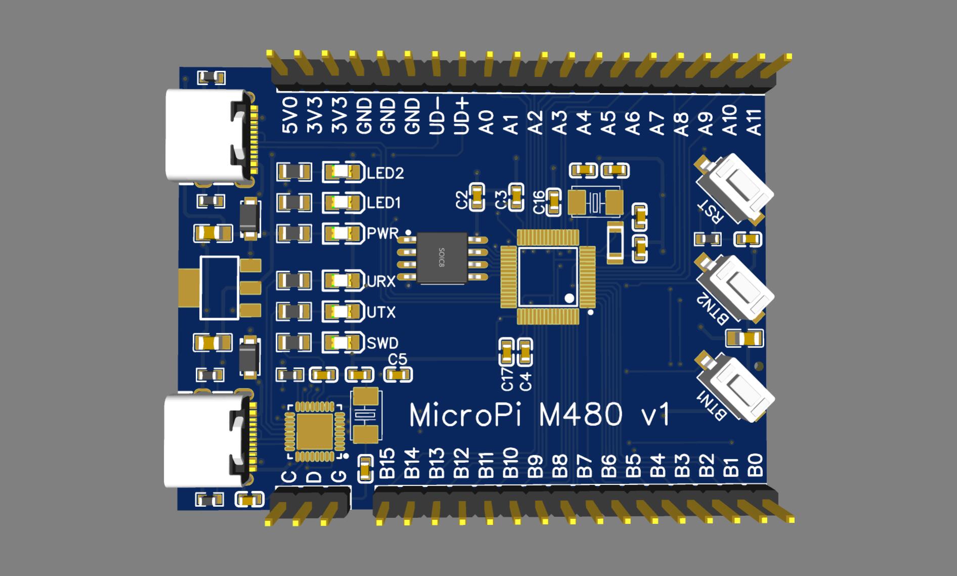
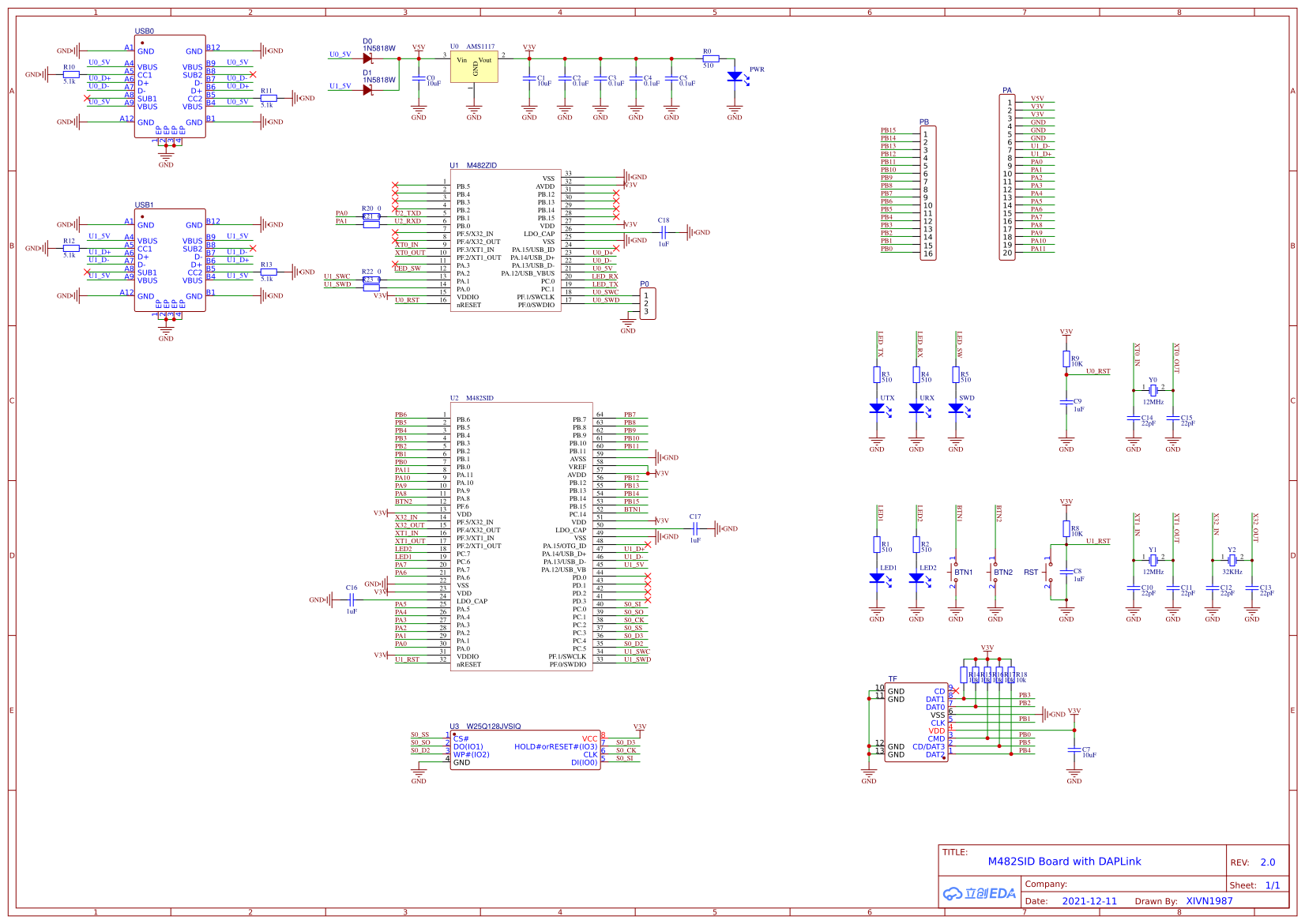
#137 Cortex M0/M3/M4/M7 » 分享我画的M482简易开发板,板载DAPLink! » 2021-12-18 21:45:48
- XIVN1987
- 回复: 3
虽然Linux要学,,可单片机也不能丢弃,,所以画了块简单的单片机小板。。 ![]()
焊了一块测试了下,,基本功能没问题。。主控和DAPLink都能工作。。
MicroPi-M482 Github: https://github.com/XIVN1987/MicroPi-M482
MicroPi-M482 OSHWHub: https://oshwhub.com/XIVN1987/M482SIDv2
板载DAPLink的固件:https://github.com/XIVN1987/DAPLink
我给M482移植的MicroPython:https://github.com/XIVN1987/micropython/tree/master/ports/m480
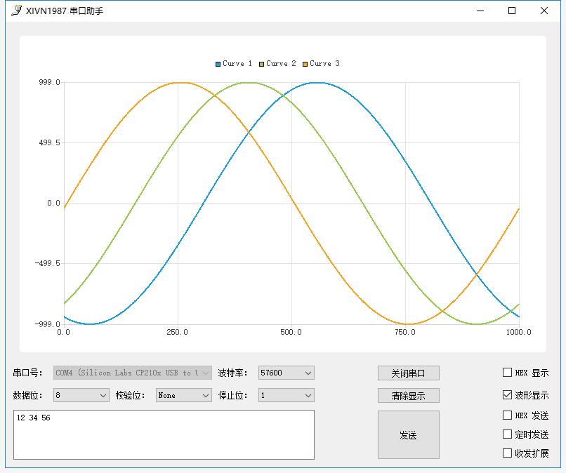
#139 Php/Nodejs/Web/HTML5/Javascript/微信开发/Python » 分享我用PyQt编写的简易串口助手。。 » 2021-12-14 13:22:42
- XIVN1987
- 回复: 3
#140 Re: DIY/综合/Arduino/写字机/3D打印机/智能小车/平衡车/四轴飞行/MQTT/物联网 » 有人会把python2 的代码转exe吗?发现个dap能接收jlink-rtt的软件 » 2021-12-13 14:15:18
这个是新版,,同时支持Jlink和DAPLink(CMSIS-DAP)
https://github.com/XIVN1987/RTTView
https://github.com/XIVN1987/RTTView/releases/tag/20211213
#142 Re: 全志 SOC » 兄弟们,MangoPi-麻雀MQ已成功量产 » 2021-12-11 13:38:30
#144 Re: PikaPython(嵌入式Python引擎) » 【pikascript】超轻量级的跨平台嵌入式Python解释器,可以在STM32G030等小资源MCU运行 » 2021-12-02 17:14:58
#145 RK3288/RK3399/RK1108 » 编译 armbian,报错 chroot: failed to run command '/bin/bash': Exec format e » 2021-11-18 21:26:41
- XIVN1987
- 回复: 1
编译命令是:
git clone https://github.com/armbian/build armbian
docker run --name c_armbian -v /root/armbian:/armbian -it ubuntu:21.04 bash
apt install git
cd /armbian
./compile.sh BOARD=rockpi-s BRANCH=current RELEASE=buster KERNEL_ONLY=no KERNEL_CONFIGURE=no BUILD_MINIMAL=no BUILD_DESKTOP=no
主机环境是 Ubuntu 18.04.4,报错内容是:
[ o.k. ] Installing base system [ Stage 2/2 ]
chroot: failed to run command '/bin/bash': Exec format error
[ error ] ERROR in function create_rootfs_cache [ debootstrap.sh:212 ]
[ error ] Debootstrap base system for current rockpi-s buster   no second stage failed
[ o.k. ] Process terminated
[ o.k. ] Unmounting [ /armbian/.tmp/rootfs-f321cf67-d4eb-4870-ad36-1313933e4c67/ ]
[ error ] ERROR in function unmount_on_exit [ image-helpers.sh:82 ]
[ error ] debootstrap-ng was interrupted
[ o.k. ] Process terminated
这个是什么问题?怎么解决??求教大佬指点,,谢谢。。
#146 Re: RK3288/RK3399/RK1108 » 编译 armbian,报错缺少 binfmt_misc » 2021-11-18 17:45:17
docker用的还是原内核,解决不了内核模块问题。必须在本机加载这个模块才行。
感谢指点,确实如此,,
只要在本地主机安装了 binfmt_misc 内核模块,在 docker 容器中就能看到,,我一直以为需要在 docker 容器中执行 modprobe 安装模块,,原来是不需要的
root@HWCloud:~# modprobe binfmt_misc

root@HWCloud:~# docker container attach c_armbian

root@91565d9071de:/armbian# modprobe binfmt_misc
modprobe: FATAL: Module binfmt_misc not found in directory /lib/modules/4.15.0-91-generic

root@91565d9071de:/armbian# lsmod
Module                  Size  Used by
binfmt_misc            20480  1
veth                   16384  0
xt_conntrack 16384 1#147 Re: RK3288/RK3399/RK1108 » 编译 armbian,报错缺少 binfmt_misc » 2021-11-17 22:26:05
试试 apt install binfmt-support
binfmt_misc 在 binfmt-support 中吗?
root@91565d9071de:/armbian# apt install binfmt-support
Reading package lists... Done
Building dependency tree... Done
Reading state information... Done
binfmt-support is already the newest version (2.2.1-1).
0 upgraded, 0 newly installed, 0 to remove and 0 not upgraded.

root@91565d9071de:/armbian# modprobe binfmt_misc
modprobe: FATAL: Module binfmt_misc not found in directory /lib/modules/4.15.0-91-generic#148 RK3288/RK3399/RK1108 » 编译 armbian,报错缺少 binfmt_misc » 2021-11-17 21:21:14
- XIVN1987
- 回复: 4
我的编译命令如下:
git clone https://github.com/armbian/build armbian
docker run --name c_armbian -v /root/armbian:/armbian -it ubuntu:21.04 bash
apt install git
cd /armbian
./compile.sh BOARD=rockpi-s BRANCH=current RELEASE=buster KERNEL_ONLY=no KERNEL_CONFIGURE=no BUILD_MINIMAL=no BUILD_DESKTOP=no
官方的编译要求如下: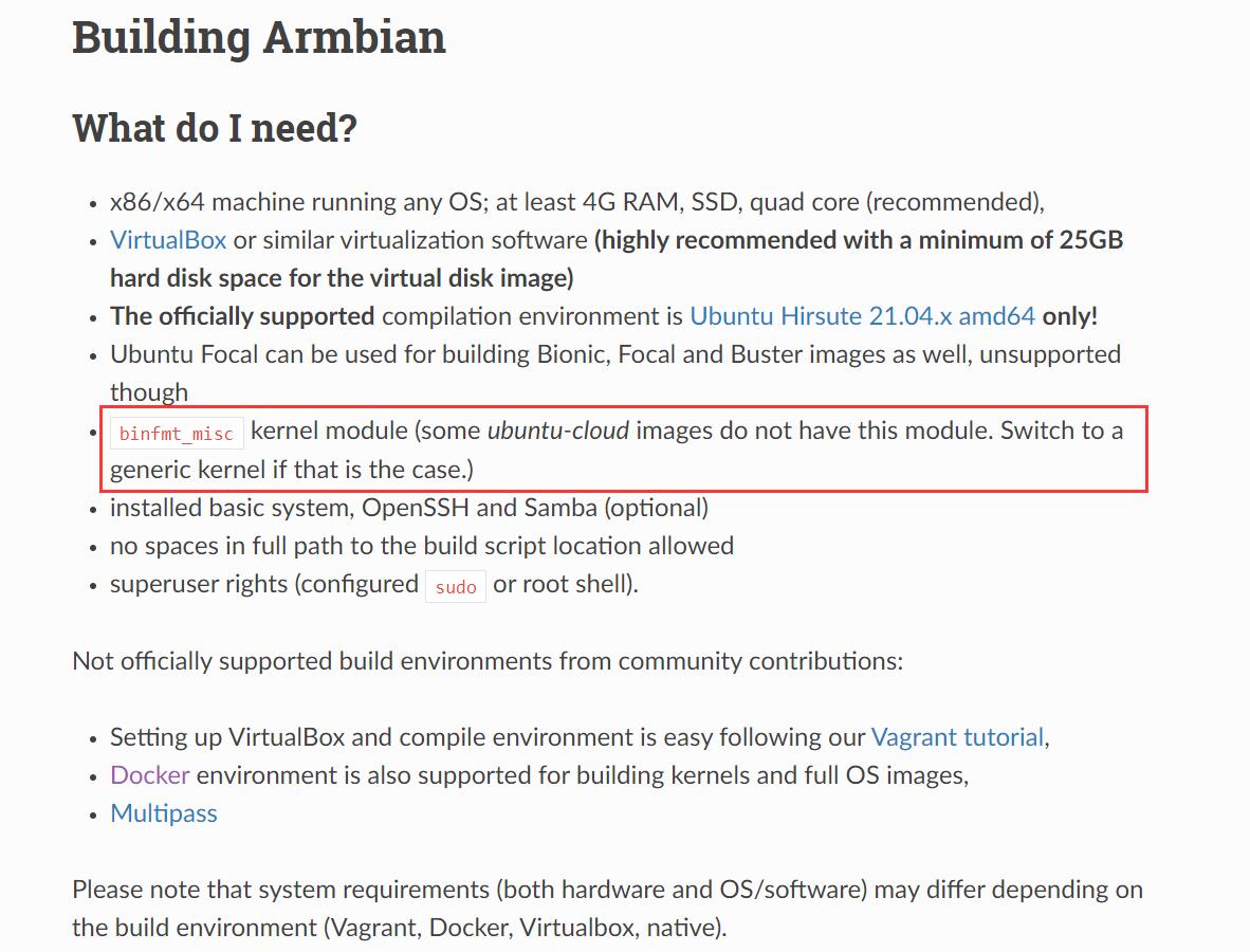
编译报错缺少 binfmt_misc,可是我使用的就是 docker hub 上 ubuntu 官方的镜像,,去哪里找有 binfmt_misc 内核模块的 ubuntu 21.04 docker image 啊?或者怎么安装 binfmt_misc?我试了”apt install binfmt_misc“报错找不到该软件。。
请求各位大佬指点,,谢谢
#150 Re: DIY/综合/Arduino/写字机/3D打印机/智能小车/平衡车/四轴飞行/MQTT/物联网 » 有没有便宜点的带usb 3.0的芯片? » 2021-11-12 10:15:02
#151 Re: DIY/综合/Arduino/写字机/3D打印机/智能小车/平衡车/四轴飞行/MQTT/物联网 » 有没有便宜点的带usb 3.0的芯片? » 2021-11-12 09:24:22
#152 Re: 技术人生/软件使用技巧/破解经验/技术吐槽/灌水 » 坐标深圳,招两个MCU软件工程师 » 2021-11-09 09:35:53
#153 Re: 全志 SOC » 【全开源/D1s】芒果派麻雀 MangoPi-MQ1 基于D1s 的 RISC-V Linux小板 【最新消息:淘宝开卖了,链接在一楼】 » 2021-10-27 16:12:18
#154 Re: RISC-V » 国产riscv芯片汇总 » 2021-10-26 14:17:31
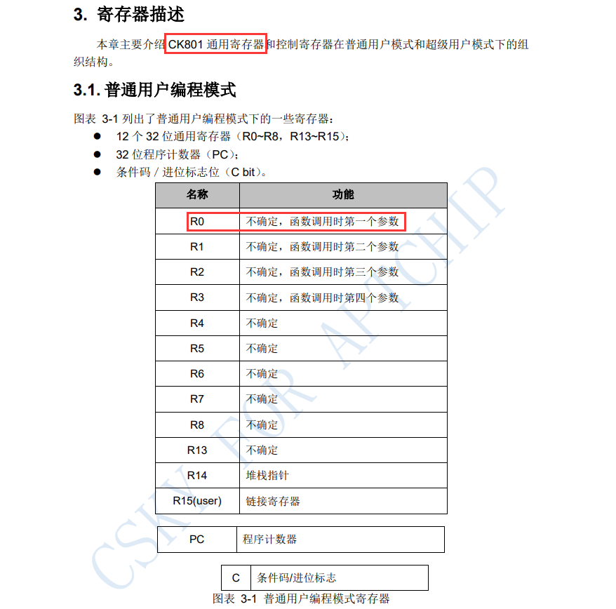
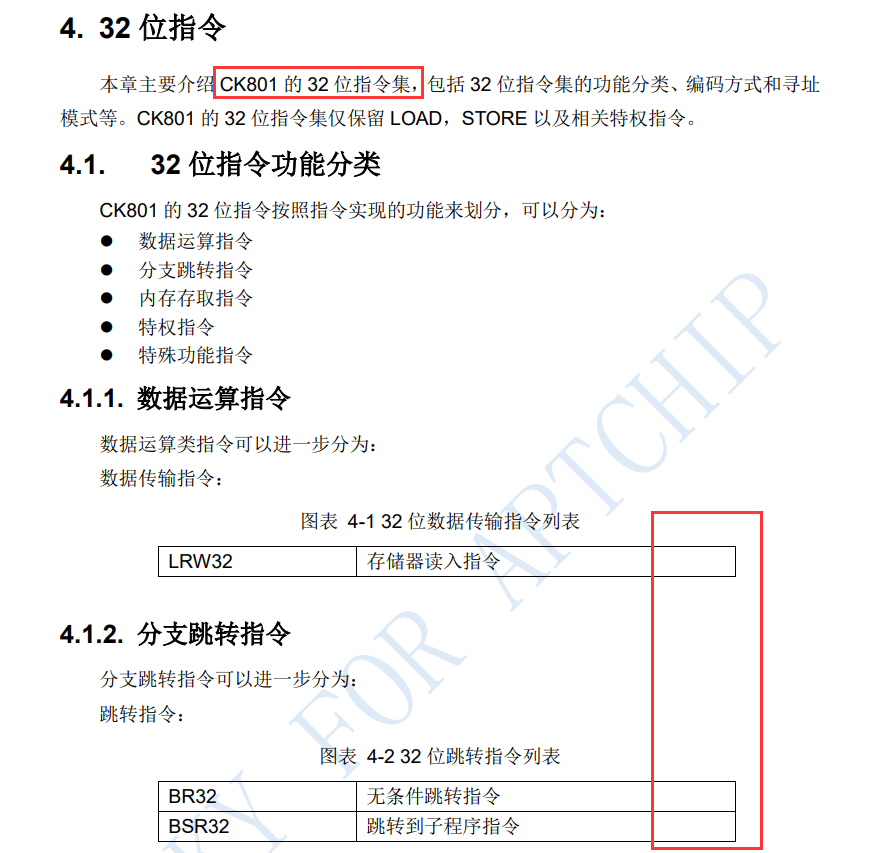
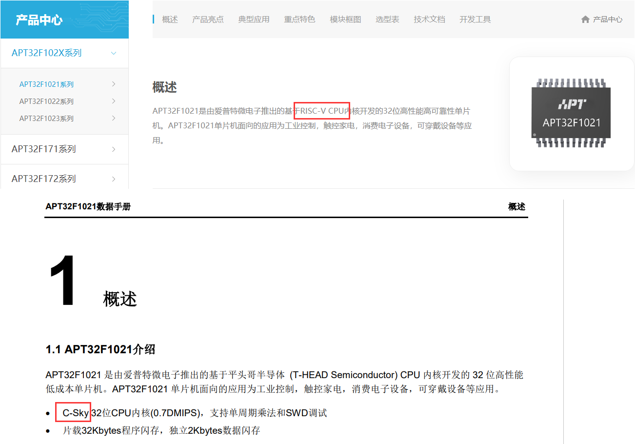
@XIVN1987
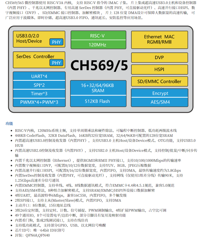
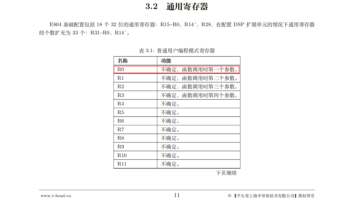
不管是8系列还是9系列都是c-sky指令集,可能版本不同分别对应v2和v3。c-sky基于riscv构建,兼容riscv。这是官方的技术特征里写明的,除非文档有误。
下面是从平头哥官网下载的“玄铁E804”手册,兼容不兼容看手册最靠谱。。
#155 Re: RISC-V » 国产riscv芯片汇总 » 2021-10-26 10:53:39
#156 Re: RISC-V » 国产riscv芯片汇总 » 2021-10-22 23:14:41
#159 RK3288/RK3399/RK1108 » WSL下使用串口助手 » 2021-09-20 19:03:12
- XIVN1987
- 回复: 1
这样串口助手和SSH客户端都能用WSL bash实现了,不在再装putty之类的软件了
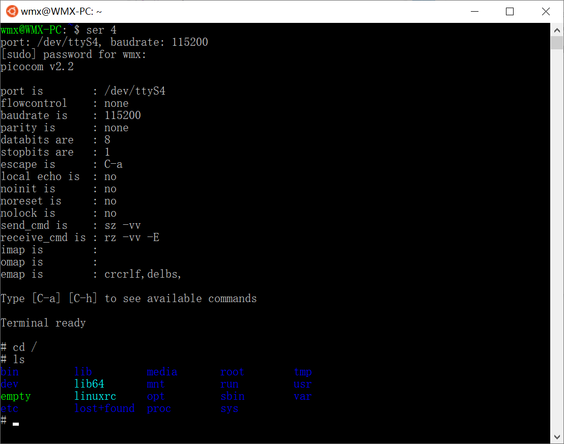
function ser {
    if   [ $# -eq 0 ]; then
        return
    elif [ $# -eq 1 ]; then
        port=/dev/ttyS$1
        baudrate=115200
    elif [ $# -eq 2 ]; then
        port=/dev/ttyS$1
        baudrate=$2
    fi

    echo "port: $port, baudrate: $baudrate"

    sudo chmod 666 $port
    sudo stty -F $port $baudrate
    sudo picocom -b $baudrate $port
}
#160 Re: RISC-V » 自制博流bl702精致小板 » 2021-09-17 13:16:03
#161 Re: 技术人生/软件使用技巧/破解经验/技术吐槽/灌水 » 怎么就管不住这买板子的手 » 2021-09-17 13:13:41
#165 Re: ESP32/ESP8266 » 除了ESP32/ESP8266还有其它厂家用Xtensa的核心吗? » 2021-09-16 11:55:02
其实SDK已经把底层都给封装好了,底层什么核心并不重要。
RISC-V只出了ESP32-C3一款而已。
又出了个 ESP32-H2,BLE + Zigbee
https://www.espressif.com/zh-hans/news/ESP32_H2?position=6&list=2Jmgp20Ks2hwxwuzBiWoW-cyTclWAsDkriUiwY4moV4
#166 Re: RK3288/RK3399/RK1108 » dw-apb-uart ff0a0000.serial: set rate:3686400, but get rate:3428572 » 2021-09-02 22:32:53
问题解决了,,解决方法:
将 drivers/tty/serial/8250/8250_dw.c 中函数 dw8250_set_termios() 里面的
#ifdef CONFIG_ARCH_ROCKCHIP
	if ((baud * 16) <= 4000000) {
		/*
		 * Make sure uart sclk is high enough
		 */
		div = 4000000 / baud / 16;
		rate = baud * 16 * div;
	} else {
		rate = baud * 16;
	}

	ret = clk_set_rate(d->clk, rate);
	rate_temp = clk_get_rate(d->clk);
	diff = rate * 20 / 1000;
	/*
	 * If rate_temp is not equal to rate, is means fractional frequency
	 * division is failed. Then use Integer frequency division, and
	 * the buad rate error must be under -+2%
	 */
	if ((rate_temp < rate) && ((rate - rate_temp) > diff)) {
		ret = clk_set_rate(d->clk, rate + diff);
		rate_temp = clk_get_rate(d->clk);
		if ((rate_temp < rate) && ((rate - rate_temp) > diff))
			dev_info(p->dev, "set rate:%d, but get rate:%d\n",
				 rate, rate_temp);
		else if ((rate < rate_temp) && ((rate_temp - rate) > diff))
			dev_info(p->dev, "set rate:%d, but get rate:%d\n",
				 rate, rate_temp);
	}
#else
替换为:
#ifdef CONFIG_ARCH_ROCKCHIP
	rate = clk_get_rate(clk_get_parent(d->clk));
	ret = clk_set_rate(d->clk, rate);
#else#167 Re: SigmaStar/SSD201/SSD202/SSD212 » SSD芯片功能差异表 » 2021-09-02 15:09:00
#169 Re: ESP32/ESP8266 » ESP8266的外设真的很拉垮 » 2021-09-01 15:53:25
#170 RK3288/RK3399/RK1108 » __PHYS_OFFSET == KIMAGE_VADDR ? » 2021-08-17 11:04:44
- XIVN1987
- 回复: 0
// arch/arm64/kernel/head.S
#define __PHYS_OFFSET   (KERNEL_START - TEXT_OFFSET)

// arch/arm64/include/asm/memory.h
#define KERNEL_START      _text

// arch/arm64/kernel/vmlinux.lds.S
    . = KIMAGE_VADDR + TEXT_OFFSET;

    .head.text : {
        _text = .;
        HEAD_TEXT
    }

因此:
__PHYS_OFFSET = (KERNEL_START - TEXT_OFFSET)
              = (_text - TEXT_OFFSET)
              = (KIMAGE_VADDR + TEXT_OFFSET - TEXT_OFFSET)
              = KIMAGE_VADDR
这两个符号一个叫“物理偏移”,一个叫“虚拟地址”,,最终却是同一个取值??
#171 Re: RK3288/RK3399/RK1108 » Devicetree Spec 上的 Specifier Mapping Example 什么意思?看迷糊了,哪位大神给讲讲。。 » 2021-08-14 07:45:01
又读了几遍,,感觉意思是:
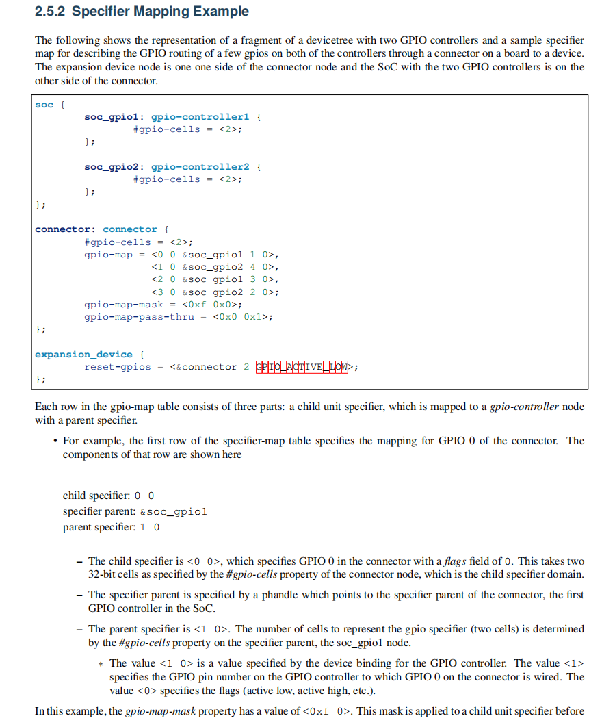
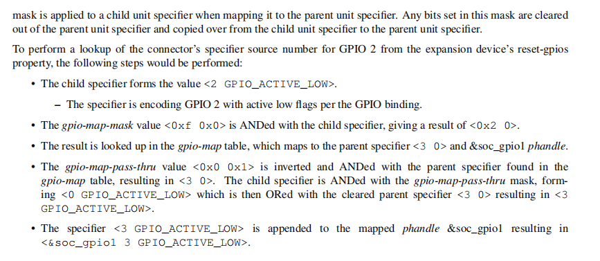
expansion_device 的 reset 使用的 GPIO 是“<&soc_gpio1 3 GPIO_ACTIVE_LOW>”,推导如下:
1、查表前先执行 mask,<2 GPIO_ACTIVE_LOW> & <0xf 0x0> 得 <0x2 0>
2、使用<0x2 0>查表,查得 specifier parent 为 &soc_gpio1,parent specifier 为 <3 0>
3、pass-thru 为 <0x0 0x1>,因此 <2 GPIO_ACTIVE_LOW> 的第二个 cell 的最低位需要无修改地从 child node 传递给 parent node,即 parent node 的第二个 cell变为 GPIO_ACTIVE_LOW
#172 RK3288/RK3399/RK1108 » Devicetree Spec 上的 Specifier Mapping Example 什么意思?看迷糊了,哪位大神给讲讲。。 » 2021-08-13 18:22:42
#174 RK3288/RK3399/RK1108 » dw-apb-uart ff0a0000.serial: set rate:3686400, but get rate:3428572 » 2021-08-07 19:57:55
- XIVN1987
- 回复: 1
linux console设置波特率115200,逻辑分析仪实测为107142,,开机打印信息如下:
[ 0.199149] Serial: 8250/16550 driver, 5 ports, IRQ sharing disabled
[ 0.201430] console [ttyS0] disabled
[ 0.201514] ff0a0000.serial: ttyS0 at MMIO 0xff0a0000 (irq = 10, base_baud = 1500000) is a 16550A
[ 0.201693] clk_uart0_frac parent_rate(24000000) is low than rate(3686400)*20, fractional div is not allowed
[ 0.201789] clk_uart0_frac parent_rate(24000000) is low than rate(3760128)*20, fractional div is not allowed
[ 0.201811] dw-apb-uart ff0a0000.serial: set rate:3686400, but get rate:3428572
[ 1.240605] console [ttyS0] enabled
是不是因为UART0时钟除以115200波特率商不是整数导致的?如果换个其他波特率的话,应该能得到准确波特率
不过如果希望继续用115200的话,,请问应该怎么设置?
#175 Re: DIY/综合/Arduino/写字机/3D打印机/智能小车/平衡车/四轴飞行/MQTT/物联网 » 启明云端分享|Sigmastar SSD202D都有哪些特点嘞~ » 2021-08-06 15:36:30
#176 RK3288/RK3399/RK1108 » 看到一个相当紧凑的SOM! » 2021-08-05 10:17:58
- XIVN1987
- 回复: 4
如下图所示,,这应该是极致紧凑了吧!
瑞芯微的芯片都是BGA封装的,,画板难度比较大,,要是能出些类似这种的SOM,,使用难度会大幅降低。。

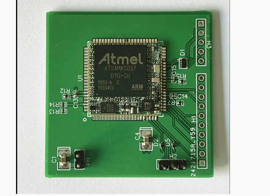
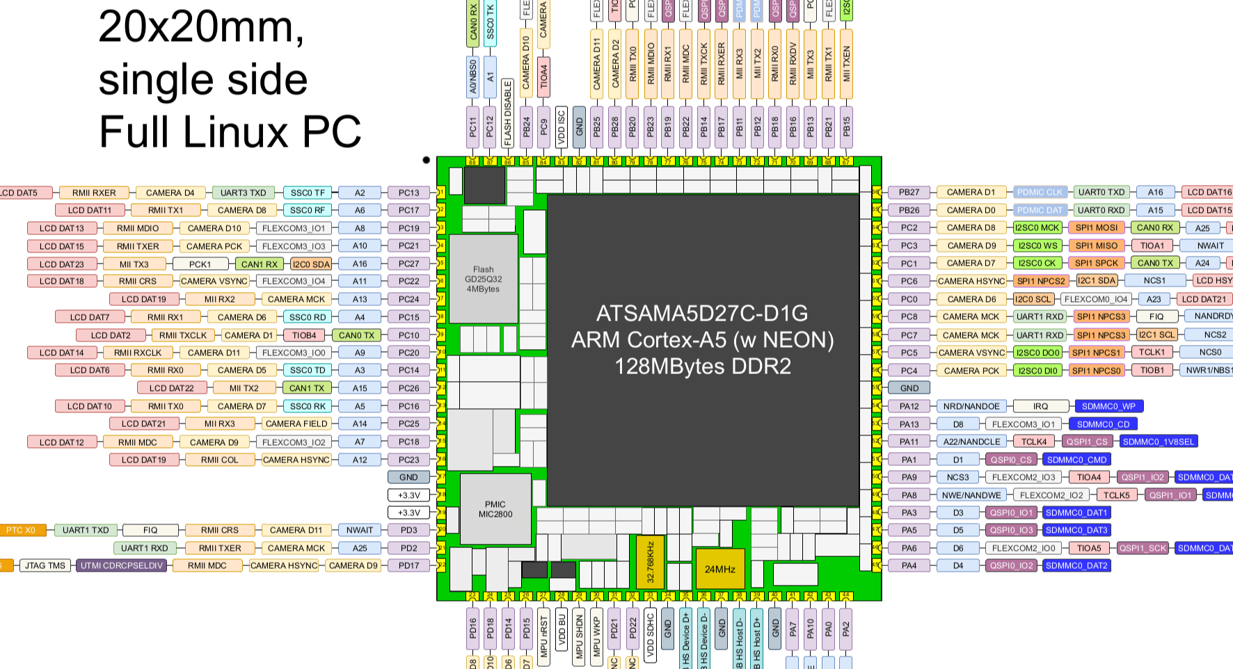
#177 Re: 全志 SOC » 有人关注MicroChi的SAMA5D2系列吗?内嵌DDR2,128Mbit ~1Gbit 都有。参考设计以及驱动等资料非常完善 » 2021-08-05 10:03:41
我上贴说错了,,不是ATSAMA5D27C-D1G叠封DDR没优势,,而是ATSAMA5D27-SOM1没把优势发挥出来
下面这个SOM就充分发挥了ATSAMA5D27C-D1G叠封DDR的优势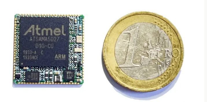
看起来SOM长宽只比芯片大了20%,,相当紧凑
#178 Re: 全志 SOC » 有人关注MicroChi的SAMA5D2系列吗?内嵌DDR2,128Mbit ~1Gbit 都有。参考设计以及驱动等资料非常完善 » 2021-08-05 09:51:11
https://whycan.cn/files/members/729/20180725_085750.jpeg
这么快就收到som,不到5天,赞。包装很专业,很仔细,也赞一个
既然DDR已经叠封在芯片里面了,,芯片的封装为什么还是BGA??完全没体现出叠封DDR的优势啊!
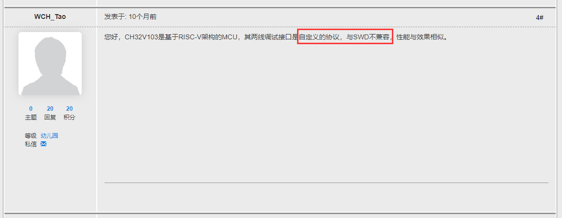
#179 Re: RISC-V » 看到沁恒的riscv单片机支持swd调试。 » 2021-08-04 18:10:27
#180 Re: RISC-V » RISC-V代码密度相比Cortex-M差距明显 » 2021-08-04 17:45:39
这篇文章说用Segger的库和连接器可以大幅减小代码,,楼主可以试下

https://blog.segger.com/code-size-closing-the-gap-between-risc-v-and-arm-for-embedded-applications/
#181 Re: 全志 SOC » [转载 aw-ol.com] 【极简操作】使用builroot 2021一键编译生成D1 nezha 系统镜像! » 2021-08-03 17:12:52
https://whycan.com/files/members/3907/2021-07-03_222100.png
突然感觉手里的 tina 不香了.
从打印信息看,启动流程是“ROM => OpenSBI => Kernel”,,没有执行U-Boot?
#183 Re: 全志 SOC » 这个开发板要取消了吗? BeagleV Starlight RISC-V single board computer cancelled » 2021-08-03 16:24:29
#191 Re: 计算机图形/GUI/RTOS/FileSystem/OpenGL/DirectX/SDL2 » 在V3S上试着跑了一下新版的LVGL-8.1 界面效果越来越赞! » 2021-06-21 11:18:16
#193 Re: ESP32/ESP8266 » ESP32-C3片子好像出来了 » 2021-04-09 17:33:53
#194 Re: Cortex M0/M3/M4/M7 » RK2108 » 2021-03-14 11:17:13
#196 Re: Openwrt/LEDE/AR9331/MT7688/RT5350 » OpenWrt vs Buildroot » 2021-02-20 15:14:25
看这里。。。
通过 v3s openwrt 上网发个帖
http://whycan.com/t_5379.html
(出处:哇酷开发者社区)
看来我搜的不够仔细,,
感谢指点
#197 Re: Openwrt/LEDE/AR9331/MT7688/RT5350 » OpenWrt vs Buildroot » 2021-02-19 15:35:09
什么源码去芯片供应商下?比如v3s移植openwrt ,''make menuconfig 选择芯片型号、开发板型号、需要的功能和软件''openwrt源码自带的吗?
有人移植就有,,没人移植就没有
比如NUC980的buildroot在芯片官方github上有 https://github.com/OpenNuvoton/NUC970_Buildroot
又如开发板RockPi S有人移植openwrt:https://github.com/jayanta525/rk3308-rock-pi-s
v3s的openwrt移植我搜了下,,确实没找到,,估计没有大神感兴趣吧
#198 Re: Openwrt/LEDE/AR9331/MT7688/RT5350 » OpenWrt vs Buildroot » 2021-02-19 15:05:44
buildroot 偏向于给你提供定制rootfs的选项,怎么选由用户来定。而且buildroot是选好了之后对源码进行交叉编译;而openwrt我的理解类似于Debian,官方给你选好了很多软件包和服务,组成了一个有特色的操作系统。当然由于带了包管理,你还是可以事后安装你想要的软件包。不像buildroot是自己编源码,在openwrt这些软件包事先都是已经编译好的,放到了源服务器上。
我感觉使用上差不多,主要都是三步:
1、git clone 下载源码
2、make xxx_defconfig(OpenWrt不需要此步)、make menuconfig 选择芯片型号、开发板型号、需要的功能和软件
3、make 编译生成linux镜像文件,,执行这一步的时候都会先根据选择的芯片编译生成交叉编译器,,然后再用交叉编译器编译系统镜像
感觉真的很相似,,
要说差异的话,似乎OpenWrt的官方源码https://github.com/openwrt/openwrt中支持的芯片型号几乎都是路由器芯片,,非路由器芯片很少
不过这似乎也不是啥大问题,,因为我们下载源码的时候一般都是去芯片/开发板供应商那里去下载,,而不是去openwrt或buildroot的github去下载
#199 Openwrt/LEDE/AR9331/MT7688/RT5350 » OpenWrt vs Buildroot » 2021-02-19 12:44:55
- XIVN1987
- 回复: 14
一直认为Buildroot是用来构建嵌入式Linux系统的,OpenWrt是一个路由器系统,,二者用途明确,应该没什么交集
最近看了下二者官方的描述,,内容如下:
Buildroot
Buildroot is a simple, efficient and easy-to-use tool to generate embedded Linux systems through cross-compilation.OpenWrt
The OpenWrt Project is a Linux operating system targeting embedded devices.Instead of trying to create a single, static firmware, OpenWrt provides a fully writable filesystem with package management. This frees you from the application selection and configuration provided by the vendor and allows you to customize the device through the use of packages to suit any application. For developers, OpenWrt is the framework to build an application without having to build a complete firmware around it; for users this means the ability for full customization, to use the device in ways never envisioned.
从官方的描述来看,OpenWrt官方对自己的描述中并没有提到路由器,,而是说自己是一个“Linux targeting embedded devices”,,这样看起来的话似乎跟Buildroot是非常类似的东西,,都是用来构建嵌入式设备上的Linux系统的
除了第一句说明自己的用途,,后面大段的内容都是在说自己的一个优势:即提供了一个包管理,,因此不用在构建Linux系统时选中所有包和应用,,而是可以分别构建系统和包,,在后面通过安装额外的包扩展系统的功能
这么看来,,似乎OpenWrt确实比Buildroot更有优势
那是不是用OpenWrt构建嵌入式Linux系统比Buildroot更好呢??
OpenWrt构建相对Buildroot有什么缺点呢??
比如是不是给芯片移植OpenWrt比移植Buildroot更困难?
#200 Re: 华芯微特 » 将NES模拟器改为电容触摸控制玩魂斗罗、超级玛丽(SWM32SRET6) » 2021-02-06 10:51:11
- 首页
- » 搜索
- » XIVN1987 发表的帖子